Saturday, 27 November 2021

QRP-LABS QDX KIT (BUILD)

A BEGINNER
BUILDING THE QDX KIT

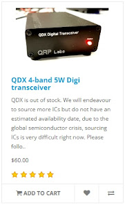
When the QRP-Labs website went live with the sale of the long awaited QDX, I was there, mouse in hand waiting to add one to the Shopping Cart, but to my amazement, the Cart told me that the product was Out Of Stock even though it had only just come online! I believe they had around 400 units and they all sold immediately. I was gutted!


To make matters worse, one of the chips on the PCB were no longer readily available, so QRP-Labs would have to try and source an alternative before they could get some more QDX's manufactured - and how long would that take?? Some people were saying that it could be months πŸ˜“

Two of my radio-club friends had been fortunate to have secured their purchase and it wasn't long before the kits dropped through their letterbox. In no time at all, one of them built his and had it up and running. The other guy decided he simply had too many things going on to build his kit - and sold it to me - hooray!! 

I was so pleased about this because I really fancied not just the product, but the building of the kit too. I'd previously built a little Transistor Radio Kit by Tecsun and found it to be a great little weekend project. The idea of building something a bit more technical (not to mention more useful) was very appealing.

So I will use this post as a brief BUILD LOG. I'm not going to go into every detail because there's some excellent Video Logs on YouTube which are far more advanced than anything I could ever do. My take on things will be about how easy (or not) the kit is to build from a beginners point of view. 

I'll highlight any hurdles and point out any pitfalls. I might even end up pointing out how everything went pear-shaped πŸ˜‚πŸ˜‚πŸ˜‚. Fingers crossed it goes well.

_____________________________


The manual for the QRP-Labs QDX Kit is a staggering 105 pages long but only the first 37 pages are related to the actual build. Following that is a really good section guiding you into the actual operation of the QDX with software such as WSJT-X. The remainder of the manual goes into great detail about the design of the product, which was way over my head!


After checking the inventory to make sure you have all the parts available in the kit, the build is split into 14 sections and starts with the installation of the ceramic capacitors. Each part of the build looks quite straightforward but I must admit to being a little apprehensive about winding all those toroids for the Transformer, Inductors and Filters. Something I've never done!


NOTE : THE FOLLOWING SECTION relating to 4 inductors no longer applies to new versions of the QDX! 

There's one other part that I'm really nervous about πŸ˜•and that's the task of removing four Surface Mount Devices which QRP-Labs discovered were causing problems in the HF region due to self-resonances (after manufacture). These four miniscule inductors have to be physically removed (by desoldering) and replaced with four new ones supplied in the kit. The tiny pads on which the SMD's sit, are incredibly easy to damage 😬.  To be totally frank, I was really disappointed to learn of this problem and I believe QRP-Labs should have made it very clear that the end-user had to tackle a job which would not normally be expected in kits of this nature. SMD stuff is very tricky to handle!

The replacement parts are thru-hole components. It would be a real challenge for a beginner like me to work at SMD level, so I opted to get a friend (G4HYG of Cross Country Wireless) to do it for me so that I could relax and enjoy the rest of the kit. 
 
Chris is a professional constructor of radio equipment and told me that he considers this QDX unit to be for Advanced builders because of the toroids, let alone the SMD work! He advised me to make the whole kit and then pass it to him to remove the 4 SMD inductors and run a Lab test to make sure I'd done everything right.

Looking around in the various forums and groups, I could see that quite a few people were having issues with failed output transistors and even the total death of the QDX. Reading between the lines, I could see that some of these failures might be attributed to the constructors choosing high input-voltage. Many people wanted the convenience of being able to use their standard 13.8V supplies and this results in a much higher power output than is recommended (potentially up to 8W), so I decided to go for the standard 9V input with up to 5W. 

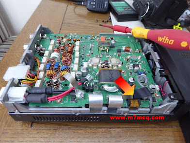
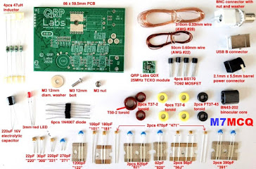
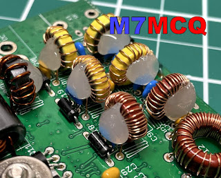
So, onto the kit. Well the first thing that smacks you in the face is the minute sizes involved! In the past I’ve built a small transistor radio kit and that was pretty compact, but the big difference here is the toroids - they’re absolutely tiny!!
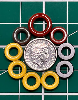
5pence piece!!

 
I’d been watching some videos of people winding these things but hadn’t really noticed their diminutive dimensions, probably because they had been using a large magnifier. Well now I can see them in the flesh and I’m more anxious than before πŸ˜‚πŸ˜‚πŸ˜‚

Anyway, I’m going to follow the Manual to the letter and that starts with fitting the Capacitors, followed by the Diodes, Transistors and then the TCXO board. After fitting anything I recommend ticking it off in the manual. Same goes for any testing that you're asked to do. Tick it off and you'll not miss anything.


With that done. it's time to do the T1 Transformer. I wasn't 100% confident with this but hopefully I've done it right πŸ™…


According to the manual, the next step is the Tapped Inductor L12, 

BUT STOP FOR A MOMENT!! 

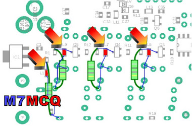
If you are a beginner to all this kit-building and in particular, winding toroids, I would strongly advise you to hold back on the L12 for a few minutes and pre-build the other toroids, L14, L2, L3, L4, L6, L7 and L10.

Why?? Because these other toroids are super simple to wind and it will be good practise before starting L12, which has 3 loops in it (taps) and it's easy to get things wrong (like I initially did).

DO NOT INSTALL the other toroids, but just build them up ready for use later and be sure to mark them with a bit of masking tape before putting them aside.


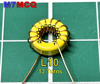
You can see in the above example (L10) that this toroid has 13 turns as counted from the CENTRE. The "FIRST TURN" is the one on the right and it is counted anti-clockwise. 

Okay, so now that you're much more comfortable winding toroids, you can start the bigger L12 feeling like you've got some experience behind you. The only difference here is that you will need to put three loops in at varying points in the winding process. I would recommend watching a video by someone called MISCDOTGEEK.

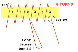
Remember to count your turns VERY VERY carefully! And remember too, that the loop goes BETWEEN the turn-numbers mentioned in the manual, so for example, as you have just completed turn 19, form a loop and then carry on with turn 20. The loop itself is not a turn!

Below is a simple example I've made up showing how a 6-TURN toroid with a Tap between 3 & 4 would look. Note how the winding starts on the left at the TOP of the toroid and ends at the bottom.


I'd like to give you a couple of tips... When you've wound the L12 Tapped Inductor and are feeling proud of yourself because you've checked it over and over and are 100% confident that it's perfect, just stop a minute and do yourself a BIG favour!

Get a Hot-Glue Gun and neatly fill the centre of the donut and give it a few minutes to cool. This will prevent the wire turns moving around as you wrestle with the toroid as you try to get all 5 termination points into the holes on the PCB. Without this, it is incredibly easy to get wires crossed over and out of alignment (I'm speaking from experience)!

It's still easy to get movement of wires on the outside of the toroid, but at least you don't have to worry about the inside wires.  When you've finished the L12 Inductor, carry on following the manual - including the continuity tests on Pg.24.

The second tip is to forget the advice in the manual about burning off the enamel with your soldering iron or using the side-cutter method. No disrespect, but beginners are very likely to do some damage with either method in my opinion. It's better to scrape the enamel off with a sharp scalpel. 

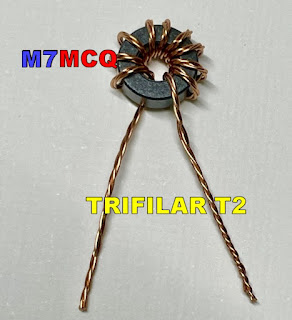
The next toroid to do is the T2 Trifilar which is super simple but you need to twist 3 lengths of wire together as one before doing the winding. The manual suggests using a couple of little screwdrivers to do the twisting but believe me, it's far easier to use a small, variable-speed drill. Put one end of the three wires into the drill-chuck and hold the other end of the wires taught with a pair of pliers and then SLOWLY rotate the drill. Make sure there's a nice neat row of twists and no kinks! 


With all the toroids installed, I would suggest using the Hot Glue Gun to help keep them all in place. Without it, they'll be quite wobbly and prone to possible damage from knocks (even when in the case).


That's it! All the other components are very simple to install and are well within the capabilities of a beginner (if you pay close attention to the information in the manual). Needless to say, the replacement of the SMD Inductors is ridiculously difficult for a beginner, so you should either seek professional help as I did, or wait for the second batch of kits which will have the correct inductors pre-installed (and the TXCO). The new versions (ie. above Ver.1) do not need this mod, so don’t worry!

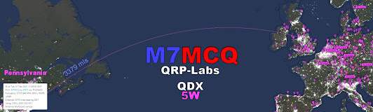
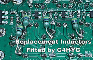
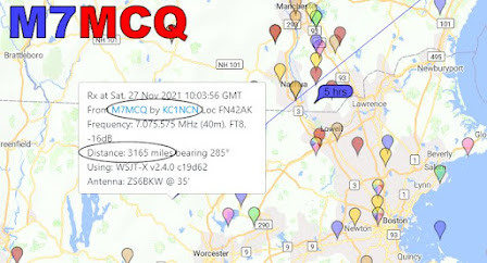
UPDATE : Chris G4HYG  replaced the tiny inductors and a few minutes ago I collected it from him. He had put the radio through its paces in his Lab and it was pushing out a solid 5W on all bands!

He also tested it in action on FT8 and reported that the 30M band sensitivity seemed slightly low but he still managed to make contacts as far away as Kazakhstan, so it's not that bad! He said it was a "Little DX machine". So my thanks to Chris for doing the SMD bits and the testing. He also tested the unit on 60M but that's a band I'm not allowed to use as an M7.


All that was left to do now was to fit the unit into its box and screw it together. Just in case the transistors started to get hot with lengthy FT8 use, I drilled a set of ventilation holes in the case, top and bottom. I very much doubt that they're going to be needed, but it costs nothing to ventilate the box does it? 


REAL LIFE RESULTS:

As a real measure of the QDX, I decided to connect it to my SotaBeams BandHopper which I'd temporarily installed in the back garden. It was setup in 40M mode which was just as well because I can only test during the evening times due to work commitments. 

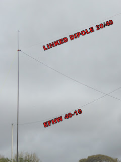
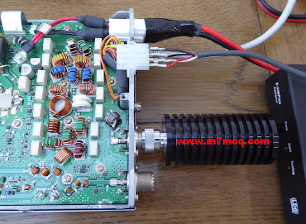
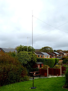
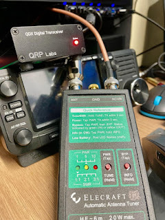
Although the BandHopper is supposedly resonant on 40M, the SWR is still slightly higher than I'd like down at 7.074MHz so I put the Elecraft T1 ATU inline to fine-tune the antenna and give the little transceiver an easy time.

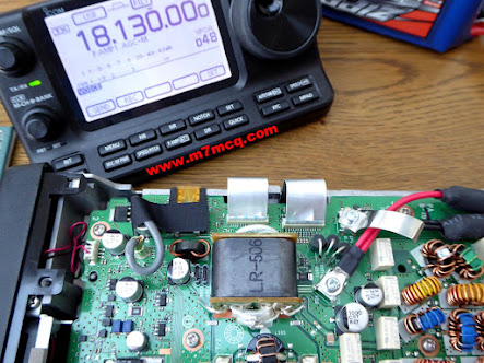
I plan to try it on an indoor Magnetic Loop later and I'll have to pre-tune the loop using another radio (probably the IC-705) to make sure it's spot on before connecting the QDX to it.

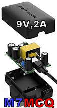
To power the radio, I used a battery which I'd purchased specifically for the QDX. It's a 7.4V Lipo with a 5,000mAh rating. That should give me a good few hours use out in the field! For home use I've got a small mains 2A PSU putting out 9V. I was pleased to see that the PSU added no noise.

7.4V LIPO

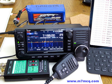
Setting up the QDX for WSJT-X was pretty straightforward and there's more than enough information in the User Manual to guide you through it if you've never used the software before. The only thing I don't like about this transceiver is that you can't reduce the power output - not even by using the Power-Slider in WSJT-X. That's a shame really, because I'd have liked to have the option to drop power right down into the mW range for experimenting with antennas and such like.


I've wrote a post on the QRP-Labs User Group to see if anyone can suggest why my receive signal seems down and hopefully they can make a suggestion as to why it may be so and how I can improve it.

Anyway, I'm just impressed that it even works! πŸ˜‚πŸ˜‚πŸ˜‚

I'll update again later.

73, Tom, M7MCQ.


UPDATE : I reheated the solder points on L12 and the receive signals are now at normal levels but 30M remains slightly low. Nevertheless, contacts can still be made on that band (although I rarely use it to be honest). 20 & 40 are my favourite bands for FT8 πŸ‘ 


UPDATE : I built a very handy little SWR BRIDGE to protect the QDX finals from any high levels of reflected power during the "tune-up" procedure. It's a fantastic kit and incredibly easy to build. Click HERE to see more details.


Tuesday, 23 November 2021

TINY ELECTRONICS SHOPS

AKIHABARA HEAVEN

I saw a photo on QRZ.NOW which made me smile. Some photos just do that to you and you probably can't even explain why! Anyway, I discovered that this tiny little electronics store was in Tokyo - a place called Akihabara. I now want to go there πŸ˜‚

Loading...

A quick Google revealed a few others in the area. This is one of the reasons that I simply must visit Japan before I die! Everything is crammed into tiny spaces and the place is bursting with colour and urban vibrancy.

And yet it also has so much natural beauty too. Hmmm, I'm saving up to go!


Thursday, 11 November 2021

IC-7610 EXTERNAL KEYPAD

EXTERNAL KEYPAD
FOR VOICE/CW MEMORIES

DIY EXTERNAL KEYPAD IC-7610 /  IC-705

All the latest Icom SDR transceivers have the facility to store a number of brief VOICE, CW, PSK or RTTY recordings to re-transmit at the push of an onscreen button. The biggest benefit of this facility is when you're participating in a competition and don't want to keep repeating your CQ Call over and over into a mic or through a key.


Depending on the mode you are in, a different set of buttons appear on screen. You may choose to record different messages in there such as...

T1... CQ CONTEST CQ CONTEST, THIS IS M7MCQ CALLING CQ AND STANDING BY

T2... CQ 20 CQ 20 CQ 20 THIS IS M7MCQ CALLING CQ AND STANDING BY

T3... CQ 17 CQ 17 CQ 17 THIS IS M7MCQ CALLING CQ AND STANDING BY

You get the idea! πŸ˜‚ Pressing the on-screen button transmits the message once, but if you hold the button for a second, the transmission will go into a loop with a predetermined pause inbetween transmissions.

It's a great facility but the buttons take up a lot of screen space which makes your waterfall virtually redundant. The way around this is to buy or build an external 8-Button KeyPad that you can use instead of the screen buttons.  Such a keypad can be connected to a 3.5mm stereo socket on the back of the radio marked EXT KEYPAD. 

I decided to make my own keypad and ordered a suitable enclosure and buttons from an eBay seller. I also ordered a few resistors (values listed at end of the post). They were super cheap and quick to arrive. 

Now there's an advantage and a drawback to choosing a small enclosure - a small one will look real neat and will occupy very little space on your desktop (a big issue in my tiny shack). The disadvantage of a small case is that there is no room for any sort of labelling, so you pretty much have to remember what is stored in each of the 8 buttons.

That's not a massive issue for me because I have a small laminated card pinned to the wall, showing what's stored where. Once I've used the KeyPad for a couple of weeks, I'll no doubt edit it. 


Construction : The first job was to drill the 8 holes in the lid of the enclosure to match the diameter of the switches - 12mm in my case. I had chosen these particular buttons because I liked their domed appearance and the colour-coding. Initially, I tried a 12mm drill bit which immediately ripped into the lid and damaged it. Luckily, I'd bought two enclosures so I got out the other lid and this time I used a cone-cutter (often referred to as a step-drill-bit). This worked superbly.

The only thing I did wrong, was to drill by hand! I should have used a pillar drill because although I thought I was controlling it perfectly, it turned out that the drill bit was moving slightly and as a result, the buttons are not perfectly spaced 😑. Ah well, I know for the next time.


Once drilled, it was a simple case of fitting all the buttons, being careful to align the terminals in a way that assisted the insertion of the resistors. The circuit diagram is listed in the Basic Manual of the IC-7610 (Section 13-4) and it's very easy to understand even for a dummy like me...

Circuit diagram for the IC-7610

I was going to leave out that ninth switch (shown on the left of the diagram) - it's there to act as a Mute button and I just didn't think it was useful enough to include, but in the end I chose to tag it onto the end of the enclosure. CAUTION: I noticed in the IC-705 diagram, it does not have the mute facility, so if you're building this external keypad for that radio alone, it's best to leave it out (although I'm not really sure what would happen if you left it in and pressed it) πŸ’₯πŸ’₯

And if you wish to make one of these for the IC-7300, then you only need to make half of the circuit, since the 7300 only has four memory buttons. The connection to the radio is via the Mic connector (much less convenient)...


As you can see from the images, it's just a case of connecting one side of each bank of switches with the correct value resistor and the other side with a continuous connecting wire. Then you simply connect up the wires directly to the jack plug or (as I preferred) to a 3.5mm socket.  Because the small socket was reliant on a very small ring-nut to hold it in place, I decided to provide additional stability with a Hot Glue Gun just to be on the safe side. 

>>> NOTE THE MISTAKE <<<
The red wire is soldered on the wrong side of the switch
which resulted in an inoperative unit, LOL.
Quick swap-over sorted it out.

Putting the resistors in place made me realise that the case was indeed very compact! There was little room for the last two (the 1.5Ks) so I had no choice but to bend them back on themselves and locate them in the centre of the switches. Since there was no reference to the required wattage in the circuit diagram, I bought 2W resistors and I could probably have got away with much smaller 0.5W instead 😳. 

I'm not very good at this sort of stuff, but it worked out in the end anyway. The rest of the job is very simple and straightforward and the end result looks pretty good. I just might do another one to keep in my IC-705 rucksack (and this time I'll drill correctly and use small resistors).


This was a very simple little project which was fun to make and is a very useful addition to the shack.

Thanks for visiting the Blog. Feel free to leave a comment below.

73, Tom, M7MCQ.


COMPONENT LIST

4 X 1.5Kohm  +/-5%

2 X 2.2Kohm  +/-5%

2 X 4.7Kohm  +/-5%

1 x 3.5mm Stereo Socket

1 X 12V Latching Push Button (optional mute switch)

8 X 12V Momentary Push Buttons (whatever you have)

1 x Enclosure Box (100x51x22mm is what I used)


Sunday, 7 November 2021

ONE OF THOSE DAYS!!

WHEN EVERYTHING GOES WRONG.

"Winter's coming", as they say in Winterfell. And for me, that means my gardener won't be around for a few months, which also means that I can erect temporary antennas on the lawn in the back garden and operate from a spacious conservatory instead of a cramped radio-shack. I've been looking forward to doing this and have been frustrated by the lousy weather these last few weekends. Today has been dry - very windy and very cold - but dry!

So I set out to first of all drill a hole in my conservatory wall to facilitate the antenna's coax. I was going to be drilling from the inside out, so I had to measure carefully to try and hit a mortar-line instead of the brick. I managed to do a pretty good job of it and then I fitted an enclosure.


Once that was done, I got my Sotabeams telescopic 6M pole out and erected a "Band Springer" endfed wire which (with a tuner) covers 8 bands. Once everything was sorted, I connected the antenna to my Icom IC-705 indoors and attempted to tune with an Elecraft T1. To my shock and amazement, the little Elecraft couldn't tune it 😲

I went outside and checked everything. It all looked fine, so I took the radio outdoors and connected it directly to the antenna - with the same disappointing result. I decided to dismantle the BandSpringer antenna and replace it with my BandHopper Dipole. Sadly, I got the same miserable results when I plugged it into the 705.I started to think that there was something wrong with the radio and my patience was wearing thin, so I took it indoors and dug out my Icom IC-7100.

A few minutes later I had it connected to the antenna via an LDG IT-100 Tuner.  When I switched the radio on, I noticed that the red LED on the tuner was flickering intermittently. I pressed the TUNE button and the radio switched off 😑

OMG, I could do without this! What the hell is going on?? I checked the inline fuses and they were fine, so I had no choice but to open up the radio and see if there was a fuse inside that had blown. Sure enough, there was a 5A mini-blade fuse which had gone kaput.


I replaced the fuse and tried to figure out why it had blown in the first place. It was obviously linked to the tuning procedure that I'd initiated, so I looked at the interface lead. Much to my amazement, all four leads going into the Molex connector were hanging out!!

Whoever it was at Icom who decided it was a good idea to use Molex connectors, wants shooting! They are a pathetic design and I'd like to see them banned from radios. Anyway, my very first problem was that all the wires had come out from the connector and I hadn't got a clue which wire went where.

I removed the Molex from the back of my IC-7610 but unfortunately it had different colour coding. In the absence of any other ideas, I got my multi-meter and determined which wires went to which part of the TRS and Power Jack and used my best judgement to decide how to wire it. 

Because I didn't have a spare Molex connector, I had to figure out how to remove the pins and and then had to try to 'uncrimp' the bottom of the pins so I could re-use them. Needless to say, one of the pins snapped in half because it didn't want me to have an easy time of it 😭😭😭

After a lot of cussing, I managed to get the four wires reconnected to the pins and then soldered them in place. Before pushing them back into the connector, I test-fitted them into the back of the IC-7100 to see if I'd got the wiring config right.

 
Thankfully, I'd got it right, so I pushed the pins into the Molex and all was well with the world again! Connecting the outdoor antenna resulted in a fully functioning radio and atu.

 
So now I was left with the strange problem of the Elecraft being unable to tune the antenna when connected to the IC-705. I put the 7100 away and connected the 705 again. Pressing the Tune button on the Elecraft produced a few seconds of relay chatter followed by a green LED indicating a perfect match 😲

I have  NO IDEA why it was now suddenly working and I didn't give a damn either - I was just glad that it was! I shook my head and started to make some contacts.


The SotaBeams BandHopper Linked Dipole was working well. It was oriented toward North America and I had closed the links so that it was resonant on 40M. The tuner would take care of 20M. In fact, both the Elecraft and the LDG had no trouble at all tuning from 80 to 10m (including the WARC bands) πŸ’ͺ.

So there we have it. I've got the IC-7610 in the shack connected to a good EFHW and can use the IC-705 or IC-7100 in the conservatory. Happy days. The wife thinks I've got enough antennas up and is wondering what I'm going to be doing with our old parasol. Hmmm 😏


Thanks for visiting. Please feel free to leave a comment below.

73, Tom, M7MCQ.

Friday, 29 October 2021

ICOM IC-7610 REWIND

OOPS! I DID IT AGAIN!

Without any doubt at all, the best radio I have owned is the ICOM IC-7610. But the grass is always greener and so even though I loved my IC-7610, I thought there might be something better out there. I purchased a YAESU FT-DX101D and really disliked it. 

Obviously, it was a magnificent transceiver (as they all are at this price level), but I just couldn't believe how annoying it was to work with. No point going on about it - just read the review and see for yourself. It obviously suits a lot of people - but it didn't suit me. After that I invested in a bit of Russian technology in the form of an Expert Electronics MB1 Prime. Again, a fabulous radio, but I hit a problem which led to me returning it and getting my money back.

For a very short time, I convinced myself that I didn't need a BIG radio in the shack because most of my radio-time was actually spent outdoors with my IC-705, so I ended up "making do" with a Yaesu FT-891 and my Icom IC-7100 for indoor play. To be fair, they’re both fabulous!! 

But I kept pining for my 7610. It had just done everything so well. Nothing at all annoyed me about it. I never felt that it was lacking in any way. And as is often the case, I kept seeing IC-7610's on the internet in Groups, Forums and Blogs, making me wish I had that happy feeling back. πŸ˜‚

Well now I do! Because I've bought another one and (I know I've said this before) it's a keeper! Having first-hand knowledge of what's out there, I no longer need to look for the best - it's right here in my shack…

ICOM DREAM MACHINE

When I originally considered buying an IC-7610, I had looked at the FT-DX101D and came to these initial conclusions…

  • I hate the 101's chavvy 3D waterfall!
  • I dislike the 101's 2D waterfall.
  • I love the 101's overall appearance.
  • I love the 7610's progressive tuning.
  • I like the 7610's meter options.
  • I like the 7610's screen layout options.
  • I like the 101's 3 antenna ports.
  • I love the 7610's built-in network server.
  • I love the 7610's  4 USB ports.
  • I love the 7610's Remote Control capability.
  • I love the 7610's QSO recorder.
  • I like the 7610's compact dimensions
  • I like the 7610's TWIN CLOCKS (Local/UTC) (FT-101D has none!!)

I should have trusted my gut feeling about the 101, because having owned both radios I now know that the 7610 is the better radio for me. In fact, it’s becoming increasingly clearer that I have a strong preference for Icom’s way of doing things and find myself more and more at odds with Yaesu - especially with their newer products. 


No one can accuse me of bleating on about a product that I haven’t paid hard-earned cash for. I’ve forked out good money for them all and I look at them without any bias and without any favour. And I’d like to say that I’m not a blind ICOM ‘fan boy’.  I’m not a Yaesu hater too - I have had more Yaesu radios than any other make and I currently own four Yaesu!! 

18 Feb 2022 : I bought an LDG MC-7610 for the radio and it looks great. CLICK HERE to see.

I’m a very happy chappy and super excited having the 7610 back 😊

73, Tom, M7MCQ.