BUILDING THE QDX 'REV2' BOARD
I recently built the Original QRP-LABS QDX (Rev-1) and everything went very well. It was an enjoyable kit and so I thought I'd purchase the Rev.2 board so I could keep one in the shack and stick one in my 'go-bag'.
I'll state right now that this build did not go well initially - there were problems which drove me nuts and I later found out that it was nothing to do with anything that I'd done - it was a fault on the PCB.
I chose to record all the details of the build (and the struggle) so that anyone else who experiences similar problems may benefit. Bear in mind that this is written from the perspective of a BEGINNER with virtually no electronics knowledge. So here we go....
 |
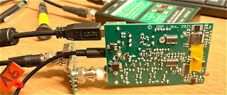
| Part built |
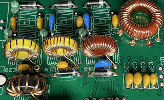
29 DEC 2021 The QRP-LABS QDX Rev-2 didn't take long to arrive and I was happily putting it together over the Xmas holiday break. Although I know nothing about electronics, I do have a good mechanical aptitude and I'm perfectly capable of soldering components together, whether they like it or not 😂This updated kit thankfully didn't have any SMD parts to worry about and I found it extremely easy to build. If I say so myself, I did a great job of all the toroids and was especially proud of my L12 with its awkward taps. It was much neater than the first one I did.
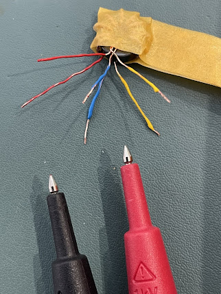
It fitted onto the PCB like it was made to measure and I experienced no problems. Neither did I have any problems with the trifilar T2. I took my time with it and made doubly sure that I had the correct A-A, B-B and C-C. I even went to the trouble of colour-coding them with a touch of acrylic paints (my other hobby is painting) 😊
After a few hours, the kit was finished and ready to plug in. Everything had gone together really well and I wasn't expecting to have any operational problems with it. I had followed the newly revised Assembly Manual (V1.08) to the letter and had carried out all the prescribed checks along the way._________________________________________________
WINDOWS 11
FIRMWARE 1.03
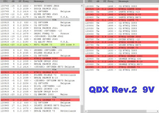
BUILT FOR 9V OPS
Before I loaded WSJT-X, I decided to run the PuTTY app and try some tests. The first test I chose was the Transmitter test. Using a SotaBeams Dummy Load and an MFJ-813 meter, I could see that it was putting out a solid 5W.The main LED was flashing 3 times during tx, as it should.
TIP : If you can't make out how many times the LED is flashing, record a video of it on your phone and play it back in slow motion.
I then chose to run the Audio Filter sweep. The results were not good at all 😢...
Next up was the RF FILTER sweep and I wasn't expecting anything good from it. I was right to feel that way because ever time I ran it, it swept up to 100% and then completely locked up. Ctrl-Q didn't work and I had to force the whole app to terminate. This app works perfectly with my Rev.1 QDX.
Feeling very dejected, I decided to do a Factory Reset but I knew it was a waste of time because I'd not actually altered anything in the first place that might cause an issue! Needless to say, it made no difference, so I decided to run WSJT-X. Well I wasn't really prepared for what I saw.....
Jeez!! What was going on????
I powered down and looked at the PCB again. Everything seemed perfect! I used a huge magnifier and a strong headlight to examine for stray solder traces, but there were none. I know this is not exactly a beginners-kit, but it's not rocket science to insert components into a PCB and solder them, is it??
I was puzzled and the ONLY thing that I could possibly have done wrong is the trifilar T2. Maybe after all that colour-coding I'd got it wrong??? No way! But it was the only component that had the potential to go wrong. So I got my multi-meter out again.
Doing the recommended A-A, B-B and C-C checks for continuity, showed no issues. Continuity was present in all three checks. BUT THEN I noticed that there was continuity between all the contact points 😱
I checked the manual to see if I'd missed any instructions to check for NO CONTINUITY between A-B-C. There wasn't any. So I was in a dilemma. Should there be continuity between all these points???
I had no choice now but to cut T2 off and desolder the bits left in the pcb. I then proceeded to carry out a continuity-check on the bare contact points on the pcb where T2 sits. I found that there were indeed some continuity between some of the contacts (see videos below).
WHILE I HAD T2 ON THE BENCH, I tested it with the multi-meter to confirm that there was only continuity where there should be (A-A, B-B, C-C) and nowhere else. The test was all clear. So this gave me the comfort of knowing that I hadn't got it wrong.
Since there was nothing else I could do, I rewound T2 and after checking I'd matched up the correct pairs (over and over and over), I reinserted the toroid and tried it out using PuTTY and WSJT-X.
Same results 😡😭😡😭😡😭
I have no idea what's going on. I can only hope that Hans (or some of the other clever guys in the GROUPS.IO) can offer some help. I'm totally cheesed off and puzzled.
Another test done (at the helpful suggestion of a GroupIO member) was to test R18 which came back as ZERO resistance. That was with T2 removed.
I'll update when there's something new to say. 😰
73, Tom, M7MCQ.
UPDATE 3 JAN 2022
Since Hans has not had time to respond with any suggestions or instructions to take measurements at specific points, the project has pretty much come to an end and I'll just have to forget about it for now and revisit it later - no point keep stressing over it when there's nothing further to be done at this time.
Thankfully, I have my original Rev1 QDX build to play with. That works superbly.
UPDATE 6 JAN 2022
I’ve had plenty of amazingly positive and helpful comments on GROUPS.IO trying to help me resolve the issues (along with the odd smartass remark), so I’ve decided to forge ahead with diagnostic and repair efforts. More later….
UPDATE 9 JAN 2022
At the suggestion of members of the GROUPS.IO, I had measured the voltage on IC3 and IC4…
IC3 PIN9 = 2.5V
IC4 PIN7 = 0V
IC4 PIN9 = 0V
I was advised to remove C38 (which appeared to be shorted) and retest IC3 & IC4, so I did…
IC3 PIN9 = 2.5V
IC4 PIN7 = 2.5V
IC4 PIN9 = 2.5V
Since I don’t own an LC Meter, I couldn’t measure the value of the C38 cap, but it certainly displayed a short.
This thing has been a Major PITA and I have been so frustrated with it all compared to my Rev1 which is running superbly.
It turns out that the board I received from QRP-Labs had this dodgy cap right from the start, so I’ve ended up wasting lots of my precious leisure time. I can’t deny being a bit miffed about it all. I wish I could just start afresh with a new board! I cannot even imagine soldering an SMD cap back in!
Anyway, I’ll just have to send a support ticket in and see what happens.
My next update will hopefully be my last one (and a positive one).
M7MCQ.
UPDATE 14th JAN 2022
The End Game!
After submitting a Support Ticket to Hans via the official website, I received a reply telling me that it would be extremely rare for a capacitor to fail, let alone as a short (even though I'd already said the cap WAS shorted out). He said he could see four possible options....
1) Find someone (in UK) who can solder on a new C38 (SMD)
2) Return it to me in Turkey to solder on a new C38 (SMD)
3) We send you a whole new kit - NOT a preferred option!
4) Find any similar capacitor, or higher value, which is an ordinary through-hole component, and solder one end of it to the appropriate wire of the trifilar transformer, and the other end to a convenient nearby ground point.
Well I was already feeling a bit miffed about all this trouble with the kit, so I wasn't really in the mood for Option 1 or 2.
Option 3 might result in a wait of weeks or months for the next batch of pcb's so that wasn't an option either.
So Option 4 seemed like my only real option. So I ordered some through-hole caps and waited for them to arrive. It only cost me a couple of pounds but as usual, it's the waiting that cheeses you off, so I paid for express-delivery which cost me much more than the caps.
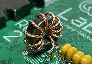
So when the caps arrived, I went to install one as advised by Hans. He said it should be fitted between the two top trifilar connections (images below). I found it quite tricky to do until I temporarily applied a blob of Blu-Tak to hold the cap in the right place until I'd soldered one leg successfully.
Once the cap was soldered, I checked the AA,BB,CC connections and all was well, so I laid down a small piece of tape to prevent the cap legs touching anything they shouldn't - just a precaution.
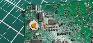
Now it was time to fit the pcb into its case and connect to a PC!
I first of all connected it to the PuTTY App and ran all the usual tests. Everything was looking pretty good apart from the 80M RF SWEEP which looks odd and I don't know how to resolve it. I reflowed L12 contact points and even tried adjusting the spacing of the coils around the 80M section but nothing has made a difference and the receive is excellent anyway.
Next up was the AUDIO FILTER SWEEP which looked acceptable to my eyes...POWER TESTS revealed a full 5W on 80, 40, and 30M but only 3W on 20M 😮
On WSJT-X the receiver was pulling in signals NO PROBLEM!! All bands pulled in lots of signal reports, so it was now time to ENABLE TX and see if I could make a contact with someone.
To my sadness, I couldn't manage a single QSO. I tried many times but not a single operator responded to my calls. I tried pouncing on the end of other contacts and then just called CQ for AGES! No contacts.
With that poor result, I looked at PSK REPORTER to see if my 5W were actually reaching anywhere and I was pleased to see that I had got as far as TURKEY ( over 3,200Km @ -19dB) from my QTH here in England . So I was getting out!
I was puzzled!! I switched over to my Tried & Tested QDX REV-1 and tried again using the same antenna, band, mode. I'm pleased to say that that too failed to make any contacts, so it was not necessarily the fault of the new build.
I will try again when conditions are better and see what happens.
73, Tom, M7MCQ
UPDATE 15th JAN 2022
FINALLY!
So, new day, new start. Plugged the QDX in and set it going on WSJT-X FT8 Mode. It wasn't long before I was making contacts. Not loads - but it confirmed that everything is working normally. You have to remember that this is a QRP transceiver and you have to work quite hard to get a contact from CQ to RR73.
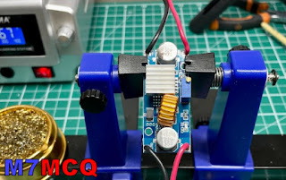
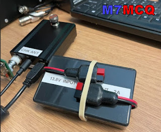
In between contacts I put together a DC-DC Voltage Step-Down unit that I'd bought on eBay. It was only £6 so I thought I'd take a chance on it. It allows me (with adjustment) to drop my Shack PSU's 13.8V to 9V. I was concerned that it might be noisy but everything seems fine and the contacts are coming in and the waterfall is showing no noise artifacts, so all good so far!
I put the little pcb into a hobby box that I'd got laying around and secured it in place with my beloved Hot Glue Gun, LOL. The specs (if you're interested) are....
Input voltage: 4-38V
Output voltage: 1.25-36V continuously adjustable
Output current:0-5A
Over 3A, attached the heat sink.(recommended for use within 4.5A for long time use)
Output power: recommended for use in below 75W
Working temperature:-40 to +85 degrees
Operating Frequency: 180KHz
Conversion efficiency: up to 96%
Load regulation: S (I)<0.8%
Voltage Regulation: S (u)< 0.8%
Short-circuit protection: Yes (the limited current is 8A)
Over-temperature protection: Yes (automatic shutdown when over-temperature)
 |
| 16 JAN - UK to JAPAN on 4W 😃 |
So, here we are at the end of what was a problematic build. At one point I was just going to abandon the kit because I value my time too much to waste it on things I can't seem to repair. It was only because of the encouragement of some of the members of GROUPS.IO that I persevered.
Lots of people tried to help me and most members were extremely kind and encouraging - THANK YOU!!!
I should give special mention though, to one particular individual who not only helped me, but who also helps everyone!! He must spend an enormous amount of his spare time helping people out. That person is Evan Hand (AC9TU). He helps and guides people without a hint of sarcasm or smartass remarks. THANKS EVAN!!!
If you have any comments or questions, please leave a message below. And thank you for visiting my Blog.
73, Tom, M7MCQ.


3 comments:
Good Job... Nice write up... Dave ~ G8LIY
I found your journey with the qdx interesting.
I have problems with mine. The rf sweeps dont look like the manual and im loathed to take components off again.
I will check some of the items you checked.
Mine shows FT8 signals but only had one qso with a germain station so not impressive.
Thanks for the kind comments guys.
Bob Stobbs- the REV2 drove me nuts and very nearly ended up in the rubbish bin, but the Rev1 went together perfectly. Thankfully, they are both performing well now.
Thanks for visiting the blog - it’s appreciated. 73, Tom, M7MCQ.
Post a Comment