
EXTERNAL KEYPAD
FOR VOICE/CW MEMORIES

All the latest Icom SDR transceivers have the facility to store a number of brief VOICE, CW, PSK or RTTY recordings to re-transmit at the push of an onscreen button. The biggest benefit of this facility is when you're participating in a competition and don't want to keep repeating your CQ Call over and over into a mic or through a key.

T1... CQ CONTEST CQ CONTEST, THIS IS M7MCQ CALLING CQ AND STANDING BY
T2... CQ 20 CQ 20 CQ 20 THIS IS M7MCQ CALLING CQ AND STANDING BY
T3... CQ 17 CQ 17 CQ 17 THIS IS M7MCQ CALLING CQ AND STANDING BY
You get the idea! 😂 Pressing the on-screen button transmits the message once, but if you hold the button for a second, the transmission will go into a loop with a predetermined pause inbetween transmissions.
It's a great facility but the buttons take up a lot of screen space which makes your waterfall virtually redundant. The way around this is to buy or build an external 8-Button KeyPad that you can use instead of the screen buttons. Such a keypad can be connected to a 3.5mm stereo socket on the back of the radio marked EXT KEYPAD.
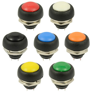
I decided to make my own keypad and ordered a suitable enclosure and buttons from an eBay seller. I also ordered a few resistors (values listed at end of the post). They were super cheap and quick to arrive.
Now there's an advantage and a drawback to choosing a small enclosure - a small one will look real neat and will occupy very little space on your desktop (a big issue in my tiny shack). The disadvantage of a small case is that there is no room for any sort of labelling, so you pretty much have to remember what is stored in each of the 8 buttons.
That's not a massive issue for me because I have a small laminated card pinned to the wall, showing what's stored where. Once I've used the KeyPad for a couple of weeks, I'll no doubt edit it.

The only thing I did wrong, was to drill by hand! I should have used a pillar drill because although I thought I was controlling it perfectly, it turned out that the drill bit was moving slightly and as a result, the buttons are not perfectly spaced 😡. Ah well, I know for the next time.

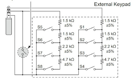 |
| Circuit diagram for the IC-7610 |
I was going to leave out that ninth switch (shown on the left of the diagram) - it's there to act as a Mute button and I just didn't think it was useful enough to include, but in the end I chose to tag it onto the end of the enclosure. CAUTION: I noticed in the IC-705 diagram, it does not have the mute facility, so if you're building this external keypad for that radio alone, it's best to leave it out (although I'm not really sure what would happen if you left it in and pressed it) 💥💥
And if you wish to make one of these for the IC-7300, then you only need to make half of the circuit, since the 7300 only has four memory buttons. The connection to the radio is via the Mic connector (much less convenient)...

 |
| >>> NOTE THE MISTAKE <<< The red wire is soldered on the wrong side of the switch which resulted in an inoperative unit, LOL. Quick swap-over sorted it out. |
Putting the resistors in place made me realise that the case was indeed very compact! There was little room for the last two (the 1.5Ks) so I had no choice but to bend them back on themselves and locate them in the centre of the switches. Since there was no reference to the required wattage in the circuit diagram, I bought 2W resistors and I could probably have got away with much smaller 0.5W instead 😳.
I'm not very good at this sort of stuff, but it worked out in the end anyway. The rest of the job is very simple and straightforward and the end result looks pretty good. I just might do another one to keep in my IC-705 rucksack (and this time I'll drill correctly and use small resistors).


This was a very simple little project which was fun to make and is a very useful addition to the shack.
Thanks for visiting the Blog. Feel free to leave a comment below.
73, Tom, M7MCQ.
COMPONENT LIST
4 X 1.5Kohm +/-5%
2 X 2.2Kohm +/-5%
2 X 4.7Kohm +/-5%
1 x 3.5mm Stereo Socket
1 X 12V Latching Push Button (optional mute switch)
8 X 12V Momentary Push Buttons (whatever you have)
1 x Enclosure Box (100x51x22mm is what I used)
8 comments:
Well done Tom, very nice made. And very handy. Personally when I'm in a competition (contest!) I almost always use N1MM contest software. You can program the function keys to play the voice recordings from the IC-7300/7610/705. I've seen others on fb that made this but yours certainly is one of the best. 73, Bas
Good morning Tom, excellent post!!! I have gone over and over the 7610 basic and advanced manuals just to get the most out of the radio. For some reason, I just never paid any attention to section 13-4. I was even at one point looking at DX Engineering's version of a push button pad. I would be kicking myself now if I had put out the money for one. Thank you very much for the post, and I am going to be spending my spare time sourcing this out.
73,
Mike
VE9KK
Looks great well done. Did you do a video demo? 73's de ON8EI
Thank you for your very kind words Bas. I've not got into competitions yet, but I really want to try it when I get some spare time :-)
Thanks for visiting.
Kind regards, Tom, M7MCQ.
Hi Mike,
I remember seeing this when I first got my 7610 but didn't get around to making one. It was a super simple project and I guess the best part of doing it yourself is that you get to choose the appearance yourself. My choices are probably not to everyone's liking, but it adds a splash of colour to the shack, LOL.
Thanks for visiting.
Kind regards, Tom, M7MCQ.
Hi there!
No I didn't make a video but I'm about to make another one for my 705 so I might do a video then John.
Thanks for visiting.
Kind regards, Tom, M7MCQ.
Great project, I made one for the 705 and FTDX-3000
Two great radios John! Thanks for the visit :-)
Post a Comment