Size wise, the Explorer is bigger than I thought - it measures approximately 6" x 4" with a decent 2-line LCD screen just under 3" wide. There’s only a single control on the front panel which, from an ergonomics point of view, is less than ideal. It has a decent built-in speaker.
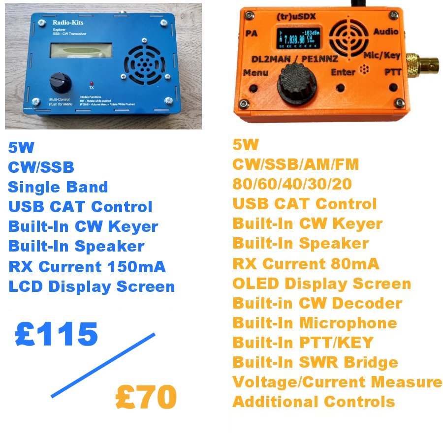
The kit cost me £115 plus postage. I guess the closest radio to this that I already own is the (tr)uSDX which is also available in kit form (£70) and is also a 5W CW/SSB Transceiver, but the big difference between them is that the (tr)uSDX is a 5-band radio while the Explorer is only single band. The 'orange wonder' also has quite a few extra useful features which are lacking on the Explorer.
Maybe the Explorer's receiver is a far better performer than the (tr)uSDX - I don't know yet, but we'll soon find out I guess.
The kit itself arrives in lots of sealed bags, separating components and keeping things organised. There are probably over 800 solder-joints to be made in this full kit, so that's a lot of soldering!! Thankfully, there is no SMD work.
Broadly speaking, the construction manual looks well written and includes great diagrams and photographs. Because it's a mono-band radio, there are only three circular toroids to wind, but there are five inductors/transformers - T4 and T5 being trifilar. Looking at that part of the manual, I'd have to say that the winding instructions would be challenging for an outright beginner. Then again, some might say that a beginner should not attempt something as complex as this kit. I'll try to include clearer explanations of the winding process to make it more understandable for any newbies reading this. Note that the 80M kit requires twice as many windings on T37-6 than the 20M kit, so it’s that much more difficult.Just like I did with the QDX KIT and the QCX KIT (amongst others) I will post on here throughout the build process, showing warts and all. If I mess something up, I will declare it and I will tell you how I got around it (or how it all ended right there). If it ends up in smoke, then so what? There'll be no tears. This isn't a $2 Billion space shuttle!
This post is PART ONE which will show the build. PART TWO will be a separate post covering the testing and performance of the kit (as built by a clueless beginner 😂 )
First job was to print off the manual and in particular the PCB LAYOUT page, so that each component can be marked off as it's soldered to the board. This is a really handy thing to do and it slows you down, which is always a good thing!!
The first components to be installed are the ones from the bag marked "20M" and these include 1 resistor, 4 inductors, 11 capacitors and 8 crystals. None of these are polarised, so you can insert them any way around. My own pedantic nature forces me to insert the components in a particular way - eg all resistors are placed on the board in a manner that makes it easy to read their values - with the tolerance bands all to the right (or at the bottom if placed vertically). Having said that, I noticed later that I'd not fitted the yellow toroids all the same way 😡 I might desolder and turn it around😂
It very quickly becomes apparent that it can TAKE AGES to find things on the PCB because of how densely populated it is. Eg, I was searching for R93 for what seemed like forever. It wasn’t in an unusual place - I just couldn’t seem to see it, LOL.
Before beginning, you'll benefit from laying out your components, identifying them and marking them up so they're easy to find and there's no chance of you picking up the wrong value....
I strongly advise that you buy a PCB HOLDER like the one below to make life easier for yourself. Good lighting and a magnifier really helps too. And don't go cheap on the soldering iron - you'll need a good quality iron for this kit - one which can maintain 350+ degrees with a nice, fine chisel-tip. All these resistors are the miniature-type and much smaller than you may be used to.
Populating the board with all the resistors, capacitors and diodes is long and laborious, so it's important not to rush through - it'll just end up in tears further down the line. Checking for correct component value, correct placement and good solder joints every single time is crucial - the key to success.
Just a word of warning about the diodes - make sure you get the orientation right because one bank of diodes is oriented the same way, while other banks alternate. It's easy to get it wrong if you're not focusing.
I used to insert a few components and then turn over the PCB and do the soldering, but it's not the best way for a beginner. Far better to insert a single component and then solder it and snip off the legs. It will take longer, but it's your best guarantee of getting it all right. Trust me!
It took me a good few hours, but eventually, the bulk of the components were in place and I was ready for the winding of the toroids, transformers and inductors.
There are five tiny binocular cores and a single larger one. Start with the smaller ones. T4 and T5 are both Trifilar wound which means that instead of feeding a single wire through, you feed three wires through that have been twisted together - don't worry - it's easy!
You need to cut three lengths of different colour 34SWG wire (that's the thinnest) about 10-12" long. Put them together and twist one end tightly and solder the tip so they stay in place and are easy to thread through the core.
Then twist the three wires all along their length - I put one end into a small drill chuck and held the other end while it turned. Don't over do it and make sure there are no kinks.
You're now ready to wind the cores. T4 and T5 need 4 TURNS each and below are diagrams to explain what actually constitutes a turn....
Every time a wire goes through the core and back out, it is 1 turn. Just bear in mind that even though you are feeding through three wires at once, it still only counts as one turn each time you go through...So feed the twisted wires through the core until you have completed 4 turns, leaving approx 40mm tails at the end. Then untwist the tails so you're back to three wires each side.
Then scrape off the enamel coating using a sharp scalpel knife, before tinning the area that will be soldered. Don't scrape off the enamel too close to the ferrite!
Once you've completed that task, get your multi-meter, and make sure that you have continuity between the wires on both sides...
There should be continuity A-A, B-B and C-C, but obviously nowhere else (check)!
Now you're ready to install T4 & T5, so cut two small pieces of double-sided sticky foam pads and attach to the pcb. Feed the six wires into the relevant holes on the pcb and when you're happy with the position, lay down the ferrite onto the sticky pad.
 |
Affix two pads
|
 |
| Feed wires thru and pull gently from other side |
 |
| T4 & T5 completed! |
Next up are T1 and T3. These are easy to do - they have 4 Turns of 34SWG wire each side! So, using two lengths of wire, each about 8" long, complete 4 Turns from one side of the binocular core and then turn it around and do another 4 Turns, leaving 40mm tails both sides.
Below is an image of this type of winding showing just one turn (you need to do 4)
Like you did previously, scrape off the enamel from the ends of the tails and tin them before fitting them to the pcb and soldering them. No need for sticky pads this time.
Next up is the L2, which is the last of the tiny binoculars and this time it stands upright on the pcb. It is wound with just 2-Turns of the 27SWG wire and is super simple to fit.
And now for the big one! The T2 is easier to handle because it's bigger but it uses thicker wire. You wind this one just like you wound T1 and T3. Cut two 10" lengths of the thickest wire (24SWG) and do 4 Turns from each side.
Then add a single turn of the medium sized wire (27SWG) wire through one end. It should look like this...
When ready, carefully scrape off the enamel and tin the wires before soldering.
Now it's time to explain how you wind the circular inductors (toroids) - there are three of them and they're easy to do on the 20M version (less so on the 80M version).
If you've never wound a toroid, don't worry - there's no black magic involved. All you need to do is count the turns carefully and space them apart equally after you've completed it.
A turn is when the wire goes through the centre of the toroid, so count out loud each time you feed the wire through the hole and be mindful of the fact that the wire needs to be nice and taught - not loose and baggy - don't over stress it though.
When you think you've done the right number of turns, do a careful count - taking a photo of it on your phone can help, since you can zoom in easily.
Here's a photo of the inductors on my Explorer....
 |
| L1 and L5 need 15 turns, while L3 needs 16 turns |
The rest of the build is pretty straightforward and the supplied build manual explains it all perfectly. Just watch out though for those parts which need soldering on the underside of the pcb!!
I should point out that I didn't use the supplied heatsink - I just didn't like the look of it, so I used one that I had in the shack…
Here's some photos of the finished product, prior to testing...
So there you have it!! The next post will be all about testing the build and (assuming everything is fine) looking at the performance of the radio. Click here to read it.
Thanks for reading the post and I hope that someone benefits from it.
73, Tom, M7MCQ.


14 comments:
Wow, Tom, you've been hard at work! Thanks for the write up of the construction...I'm very much looking forward to your follow-up posts.
73,
John
Thanks John! The receiver is working spot-on with no issues. There was a contest on this weekend, so a great opportunity to receive signals from across the globe!
TXing is different - I appear to have a problem where the PA BIAS menu option keeps resetting to its default low-level, which won't produce any power. I've written to RK and they're going to put together some test procedures for me to use. Hopefully, we'll get the issue sorted out and I'll detail it all in my next post.
Take care.
73, Tom.
Wow, Tom. What a great blogpost. Very detailed. Interesting kit to build. Not my piece of cake at the moment. But for someone that writes that he has no electronic knowledge you're doing extremely well. I'm shure you're starting to learn from it! Well done! 73, Bas
@BAS : Thanks very much Bas. I don’t seem to be learning much at all, LOL, but it’s all entertaining.
Hope you’re well.
73, Tom, M7MCQ.
Good morning Tom very nice attention to detail on the winding of the toroids and on T1-T5. Very nice pictures and explanations on how it's done. Very much enjoyed reading the post.
73,
Mike
VE9KK
@VE9KK : Thanks Mike. Hope it helps someone.
73, Tom, M7MCQ.
Hi Tom, it's G6ALU the designer! I purposely reset the bias every time you go in the menu so it's not accidently set high if replacing a transistor , I can change this though if there is demand.
@G6ALU : Hi Steve, thanks for popping by! It doesn't bother me that it resets every time - I just didn't know whether or not it should do :-)
There's a lot of interest in this new kit - I'll be taking it to a 'Show & Tell' at the radio club at some point soon. I suspect you'll get a few more orders.
Best regards,
Tom.
Hi, I read your blog with interest and my Radio-Kits Explorer kit arrived today. What have you used for a microphone? I can see from page 41 of the manual that the tip of the mike plug carries the audio and bias and the ring is PTT, presumably pull-down to talk. However, I wondered which mike you cannibalised or if you bought a two wire electret and a switch. Best regards, Robert M0NVQ
@ROBERT - Hi Robert, I used a TNT Microphone that I had in the shack - I think it's mentioned in PART 2 of the review (see below)...
https://tommcquiggan.blogspot.com/2024/03/radio-kits-explorer-part-2.html
@ROBERT - Again. If you look at my (tr)uSDX review and scroll down near the bottom of it, you'll see details of the TNT and also a RETAVIS that I played around with.
ALSO, take a look at the DAVE PEGLER mic which is aimed at KX3 users. It's a fabulous little thing costing around £20 and works VERY well with the KX3. Luckily, it uses a TRRS socket, allowing you to easily make up different leads without destroying it.
https://tommcquiggan.blogspot.com/2024/09/kx2kx3-ulra-light-mic.html
@Tom, I also spotted the "1-Pin Handheld Speaker Mic Microphone For Motorola Talkabout Radio Walkie Talkie" on the auction site. It has a 2.5mm sterio type plug with audio/bias to the tip and PTT on the ring. There is also an adapter from 2.5mm to 3.5mm for £2.60. Looks like I better get moving with the kit. Great BLOG by the way. I will take on board your BLOG details as I go. Best regards.
I’m currently building the Explorer and found the microphone and adapter hints very useful. Thanks. Peter
Hi Tom,
Just finished the build of my Explorer 20m. A joy to build and even more with your colorfull made component pictures. Took me a weekend and had no issues other than two twisted wires at T5. Yes the kit is a bit more expensive (also adding the taxes at Dutch customs) but very professional offered and i like to have some 'old school' suff in the modern shack again. Thanks again for your helpfull blog.
vy 73 de Johan, PA3ANG
Post a Comment