Monday, 29 January 2024

QRP-LABS QCX KIT BUILD

CW 40M TRANSCEIVER

>>>>UPDATE<<<<

After building this unit I hit a problem and needed to order a new chip. This post is the completion of my QCX story.

PREFACE : I was recently at a Radio Rally and was moaning all day at how poor it was - full of old junk. I was helping out on one of the stands and had to stay there all day, otherwise I'd have disappeared within minutes of arriving.

Anyway, a friend had seen a BHI speaker on a stand for £100 but he said they wouldn't haggle, so I went over to beat them into submission - and it worked - so my mate bought the speaker. While I was there, I spotted a cardboard box with special Turkish stamps on it.


It kinda looked familiar, so I took a closer look and discovered that it was a small parcel from QRP-LABS similar to the one that my QDX had arrived in. I picked it up and saw that it was actually a QCX. That's a singleband CW 5W transceiver in kit-form.

I was quite excited because I just love building these sort of kits and so I nonchalantly expressed interest in it. From experience, I knew that after Tax, Import Duties and Postage, a QCX will cost a UK buyer around £100. If you want the aluminium case to go with it, the figure goes up to £130. 

Here was one with both items, boxed, unopened and even had a full colour printed spiral-bound manual (which you can't even buy) and I blagged it for £10!!!!  How good is that?? 

The seller warned me that the kit came from a Silent Key and he had no idea if all the components were present, but I knew already that there was nothing missing. It was obvious that the packaging had never been opened and it was probably one of those things that people purchase and hope to get around to building one day in the future.

It looks like the purchaser had also gone to the trouble (and expense) of having the Manual colour printed on A4 paper with spiral binding. Very nice! I was so pleased with my little find.

When I sat down to read the manual for the first time, I could see that the original buyer had done the same thing. He had very obviously gone through it and highlighted the very important parts which need special attention during the build. I'm guessing he'd read it a couple of times because there were handwritten notes in different ink/pencil. They were very neatly written and it showed that he had a previous kit-building experience.

My inquisitive nature led me to find out more about this Silent Key. I could see from the packaging that the name and address had been hidden with black marker pen, so I took a photo and then over-exposed it in software, which partially revealed the text.

I could just about make out the postcode, so I searched QRZ for amateurs in that immediate area and up popped Mark Raybould - G3XYS. He had lived in the High Peak district of Derbyshire, about 30 miles from me. 

I learned from his bio that he was first licensed in 1968 and was very much a QRP man and greatly enjoyed SOTA activities. I discovered too that he was the very first person to activate Moel Eilio, GW/NW-022 in Snowdonia, back in 2002. 


He also had an American callsign (NS1Q) and had family over there in Vermont, but that's as much as I know at this time. I was very pleased to find this connection to the QCX and it felt good to know that I'd be finishing off one of Mark's projects for him. Something which he was sadly unable to get around to doing himself - possibly due to ill health?

------ * -------

THE BUILD : Bear in mind that this is the original QCX and not the later QCX MINI. Now this kit represents a significant increase in complexity compared to the kits I've built before. Please bear in mind that I have no real knowledge of electronics and I'm writing this post to show how a beginner might cope with this kit.

There are a lot more parts than I'm used to (with almost 300 solder joints to complete) and I'll have to pay very close attention to the build-guide. Looking at the original packaging and post-mark, I can see that this was purchased in 2018 and thankfully it came with the REV.3 manual already printed out.

The last revision of the QCX is REV.5 but a quick glance at the website indicates that the Rev.3 can be brought up to date during the build with changes to components (or additions), but looking through the alterations I might not bother. 

Rev 4: (31-Oct-2018)
1) Changed C21 and C22 to 1uF (previously 10uF) to reduce click on Tx/Rx switchover
2) Kits shipped after 12-Apr-2019 changed R41 from 470 to 150 ohms; R42 from 1K to 1.2K; C31 from 1uF to 2.2uF; to improve key-shaping.
3) Kits shipped after 12-Apr-2019 also changed R21 from 7.5K to 10K to allow phase compensation for larger range of component tolerances. 

Rev 5: (06-Jan-2020)
1) Removed components R49, R50 and C39; R53 changed from 1K to 3.3K; the components were not needed since AUDIO2 DC bias is 2.5V already
2) Added R49 (1K), R50 (270-ohm) and D7 (1N4148) which are to implement a serial port for the CAT control interface


There is one mod which does look interesting and that's something which was designed by a 13yr old American operator called Maxwell Moran (W3LLA). This bright young man came up with a way of turning the QCX into a WSPR transceiver! It works by bypassing the CW Filter - and it's switchable, so you don't lose any of the QCX's original functionality.

THE FIRST JOB though is to layout and organise all the components. It’s quite a laborious task checking not only that you’ve got all the required bits and bobs, but also identifying the values. You need to know if anything is missing early on, so you can make arrangements to obtain a replacement. Nothing worse than getting to the end and finding you can’t complete your kit.

It turns out that there were a couple of 10uF electrolytics missing from my kit but thankfully, a friend from Bolton Wireless Club said he had some spare (thanks M0UFC).


There was still a bit of a puzzle to solve though, because I still had more components that were listed in the printed manual. What was going on??

I decided to examine the PCB and it was at that point I realised that this kit was actually a REV.4! It seems that the original buyer had mistakenly downloaded the wrong manual. I can fully understand why, because it's really quite complicated due to the number of manual-revisions and release dates.

Anyway, all the components now made sense and I wasn't short of anything, so I started the build.

The very first job is to wind the T1 transformer which can be really tricky depending on the band you've chosen. The 20M version looks nice and easy, but I was doing the 40M version with an additional 14 turns to go on (38+5+5+5).

The T1 goes on first because it makes the job much easier without any other components on the PCB. The manual suggests that you wind the T1 in a single run and then cut loops to create the three 5-turn sections, but I found it easier to wind the 38T, then three separate 5T's.

Regardless of which way you wind it, you're in for some fiddly work. Make sure you leave long legs so that installation is less awkward. Don't worry - there's plenty of spare wire.

IMPORTANT!!! As per the manual - "the four windings on T1 must all be in the same “sense”. There are two ways to wind toroids. You might call them left-handed and right-handed; clockwise and counter-clockwise; whether the wire goes through the toroid from top to bottom, or from bottom to top. Whatever you call it, all the four windings have to be the same, to be sure to get the phasing to the quadrature sampling detector correct".

WINDING TIP : I was pretty sure I'd counted the 38 turns as I was doing it, but when I took a photo and saw it on a large PC screen, I could see that I'd only done 37, so I added another. Checking in this way allows you to easily make a correction instead of pulling your hair out after you've soldered it onto the PCB. At this stage you don't need to worry about neat spacing of the turns - you can sort that out as you're installing it.

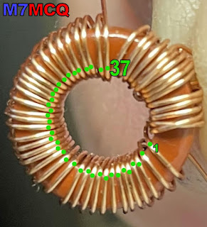
Not my best work, lol

Getting this toroid into the PCB is quite a job! There are eight straggly legs to control and it's easy to get into a mess and maybe even put the wrong wire into the wrong hole.

The ends of the 38T wire is pretty obvious to locate - the real problem is identifying the ends of the three 5T wires. To aid me with this, I put black Marker Pen on the legs of the middle 5T wire. That helped enormously. If I'd had different coloured enamelled wire, that would have been even easier!

I suggest that you start the installation by getting the innermost wires located first - 8, 4, 6. Once they're in, the rest of the job is much easier... 


With all the legs in, check that all the turns are neatly spaced and do a continuity check on the 4 wires to make sure they're in the correct holes. Once that's done and you're 100% happy with the spacings and location, you could insert a small blob of HotGlue in the center of the T1 to keep it fixed to the board and to stop any of the windings from moving around while you're snipping the legs and soldering them in place.

The manual recommends that you cut the legs down so that they're about 2mm proud of the PCB and use the Soldering Iron's heat to burn off the enamel.

Personally, I prefer to carefully scrape most of the enamel off with a sharp scalpel from the underside of the PCB before snipping the wires and then solder the 2mm legs for the recommended 10 seconds to burn off any last remnants. This method worked very well for me on my QDX but I'm no expert, so do what works for you.

Once T1 is in place, you can revert to following the start of the manual and install components accordingly.

It's worth noting that Hans has every right to tell you to check your work once, twice and even three times!  I made a mistake very early on by putting a ceramic capacitor in the wrong place. Luckily, I managed to desolder it and relocate it. 

I got into the habit of placing the components in the pcb, then taking a photo of each stage and that process slows you down a little and prevents you from rushing ahead.

The rest of the build was very straightforward - there’s nothing especially tricky - there’s just lots of it!  I simply followed the guide and before I knew it, the kit was built and ready to power-up and carry out the alignment/setup.


Sadly, when I powered up I discovered that there was a problem with the display - only the top row of text-blocks was illuminated, which (according to Hans’ trouble-shooting guide) means that IC2 is not communicating properly.

Needless to say, I checked, double-checked and triple-checked that the chip was seated properly and all pins were engaging with the socket. I also went onto IOGROUPS and got some more trouble-shooting guidance from the members there, but nothing has found the source of the problem so far.


It could be that the IC2 chip itself is faulty, so I've ordered another (£5). It’s disappointing, but the kit only cost me £10, so I can hardly complain! 

Anyway, I will try to get it going and will update this page accordingly. If I manage to sort it out, the method will maybe help out someone else who has a similar problem with this lovely kit.

Bye for now!

Tom, M7MCQ.


>>>>UPDATE<<<


The new IC2 arrived (ages ago actually, but I've been so busy I actually forgot about it) and I'm pleased to say that it resolved the screen issue, so it was the chip after all. I was worried that it might be something elsewhere on the PCB that I'd done wrong, but everything's fine.

I had to use an Arduino to do the firmware and found VK3ELH's document on the subject to be a great help.

So it’s on with the alignment - something which is detailed in the manual - no point repeating it here. Suffice to say it was the least favourite part of the build for me and I wasn’t  altogether sure I was doing it right.

If you can’t get the  trimmer capacitor plates positioned correctly during the peaking of the BPF, you might need to actually adjust the number of turns on the T1 transformer which I really didn’t fancy, but thankfully the plates were perfectly aligned meaning, I errrr, got lucky!! 😂

After this, there’s a couple of other adjustments and then you’re good to go. Time for real world testing! To play safe, I put the QCX in practise mode and inserted a paddle key.  Everything seemed to work well and I spent some time in the menus making adjustments to the standard settings and setting up some memory messages.

With an EFHW connected to the QCX I started to put out some test calls and with a small power-meter I could see that the radio was putting out around 4.2W which seems about right, so I'm very happy.

The radio includes a morse-decoder which is good for someone like me who's just setting out on the journey of learning cw. I can use the QCX not only as a transceiver, but also as a handy little practise keyer. In practise mode it will happily run on a small battery.

So why have I bought another CW Transceiver when I've not learned the code yet? Well the answer is - I love building these little kits! They're a huge source of enjoyment for me, whether I will use them or not. I guess it gives me a challenge and a sense of achievement when I complete them - if they work, lol.

I've actually ordered another one of these (secondhand) as a gift for a friend. They're excellent little units and like all the other QRP-Labs kits, a joy to build.


73, Tom, M7MCQ.

Features

  • Easy to build, single-board design, 10 x 8cm, all controls are board-mounted
  • Professional quality double-sided, through-hole plated, silk-screen printed PCB
  • Choice of single band, 80, 60, 40, 30, 20 or 17m
  • Approximately 3-5W CW output (depending on supply voltage)
  • 7-16V recommended supply voltage
  • Class E power amplifier, transistors are bolted to the PCB as a heatsink, though heat dissipation is minimal
  • 7-element Low Pass Filter ensures regulatory compliance
  • CW envelope shaping to remove key clicks
  • High performance receiver with at least 50dB of unwanted sideband cancellation
  • 200Hz CW filter with no ringing
  • Si5351A Synthesized VFO with rotary encoder tuning
  • 16 x 2 blue backlight LCD screen
  • Iambic keyer or straight key option included in the firmware
  • Simple Digital Signal Processing assisted CW decoder, displayed real-time on-screen
  • On-screen S-meter
  • Full or semi QSK operation using fast solid-state transmit/receive switching
  • Frequency presets, VFO A/B Split operation, RIT, configurable CW Offset
  • Configurable sidetone frequency and volume
  • Connectors: Power, 3.5mm keyer jack, 3.5mm stereo earphone jack, BNC RF output
  • Onboard microswitch can be used as a simple straight Morse key
  • Built-in test signal generator and alignment tools to complete simple set-up adjustments
  • Built-in test equipment: voltmeter, RF power meter, frequency counter, signal generator
  • Beacon mode, supporting automatic CW or WSPR operation
  • GPS interface for reference frequency calibration and time-keeping (for WSPR beacon)
  • CAT control serial data interface
QST REVIEW


ANTENNA SWITCH PROBLEMS

MyDEL CO-301N 3-Way Heavy Duty Antenna Switch

I was just reading something on VE9KK's Blog about buy cheap - buy twice and it reminded me of some antenna switches that I purchased from a well known ham store here in the UK. These switches are very common and I'd refer to them as mid-priced (because they're certainly not very cheap).

I purchased two of these switches and they've had very light use but one of them failed at the weekend. I noticed when detaching an antenna lead that the SO-239 was loose in the body of the switch. I had no choice but to open it up and have a look inside.

With the back panel removed, it was clear to see what had gone wrong. I had assumed that the SO-239's were screwed into the aluminium body of the switch, but they're not - they are a tight push fit and there's evidence of a bonding material (glue).

The centre-pin of the SO-239 is soldered directly to a terminal and a brass wiper arm sweeps across and makes contact with the terminal when you turn the switch.

The attaching and detaching of cables over the last 11 months has obviously stressed the SO-239 to a point where it has come loose and the twisting effect of screwing on (or unscrewing) of a PL-259 has broken the rather weak looking solder joint.

I can see from the design and the quality of the solder joint that the center connection might be the next one to go wrong. I shall have to resolder the broken one and try to add some additional bonding material to all 3 connectors to avoid them turning in the future.

These switches are about £47 each, so I don't think it's unfair to expect a little more from them. And looking at the way that the selector-blade makes contact with the SO-239's I'm surprised that you can put 1,500W through them. Wow!!


I now buy antenna switches from CROSS COUNTRY WIRELESS here in the UK. They are more expensive, but superbly made and have fantastic isolation between ports.

73, Tom, M7MCQ.

Saturday, 20 January 2024

COLIBRINANO AND IC-705

I normally use my RSPdx as a panadapter for linking to my transceivers, but today I connected the Expert Electronics ColibriNANO. I've not used it for a while and I'd forgotten how good it was. 


I used my Icom IC-705 connected to an EFHW antenna going through an LDG Z-100PLUS ATU .  The Nano and the 705 were linked via the ExpertSDR2 software, using the built-in ECATV1, but you can also use OmniRig if you wish to.


The Nano's ExpertSDR2 software is excellent and it's the perfect match for the IC-705. Setting it all up is as simple as connecting a USB lead between the PC and 705, connecting a 3.5mm stereo to stereo lead between the 705 and the tuner and finally, plugging the Nano into the PC's USB slot. This is what I love about the IC-705 - everything is just so darned easy - even a fool like me can figure it out!

Below is a brief video capture of my contact with N1W in the States...


To prevent the front-end of the ColibriNANO being damaged during a transmission, I use an MFJ-1708B-SDR which can work in two different ways. It can be activated by using a control-cable from your radio's PTT circuitry or you can rely on the MFJ's RF Sensing circuitry.  I started off by using the latter with the 705, but I wasn't happy with the slight delay in the MFJ kicking in, so I decided to make a up a control-lead.


Looking in the Advanced Manual I found information on the SEND/ALC jack plug and could see (as I already suspected) that one simply needed to use the Tip and Sleeve, so I cut the end off a 3.5mm stereo-stereo lead and fitted a Phono connector. It worked fine.

So that's it! It's a joy to use the amazing 705 with the fabulous ColibriNANO.


73, Tom, M7MCQ.

Thursday, 18 January 2024

DVMEGA CAST UPDATE

DVMEGA CAST FIRMWARE UPDATE 

I'm writing this post because there might be other idiots out there like me! I'm not much of an updater when it comes to FirmWare if I'm happy with everything I've currently got. I've seen far too many operators complaining about new firmware causing more issues than there were before the update. If it works - leave it alone.  Don't get me wrong, I'm all for improvement and will gladly update if I can see changes that I know will benefit me, but if it's for something that doesn't impact me, I don't bother.

My DVMEGA CAST has been sat in the shack unobtrusively for almost 3 years. It's sat there doing its thing quietly and without a fuss. It's on a high shelf, so even when I'm doing a shack-change, it's never in the way and never gets moved. It's almost invisible and it's certainly taken for granted. I've never updated the firmware.

But recently I stumbled across an internet page discussing the virtues of the WPSD PROJECT and when I looked further into this new digital digital voice software suite, I started to see screenshots of the DVMEGA CAST which looked totally unfamiliar to me.


It quickly came to light that I should have updated my firmware on the CAST about 6 months ago! There were really useful benefits available and I had simply been oblivious to them! 

One of the bugbears of the old firmware was the start-up times. Most times it would be pretty quick but occasionally it would take forever and go into a loop of restarting. It meant that one had to unplug the power lead from the back, wait a few seconds and then plug it back in. Another little annoyance was that the volume was always set to zero upon start-up. Other than that, I'd been perfectly happy with the unit.

Now that I have V1.32 installed (and the screen firmware has been updated too), the CAST looks like a new product!  It switches on virtually INSTANTLY and the volume is set to the default level of your choosing! Worth it just for those two changes.

But there's other benefits too, as you can see from the list in the above image. And when you add to these improvements with the WPSD frontend, it just all feels like someone's given you something for free! 😂💪

So don't be an idiot like me - remember to check your firmware regularly and see whether it's worth updating.

I already thought my DVMEGA CAST was a great little machine, but now I think it's far better. It now has a much more polished feel to it and I look forward to many more great QSO's on it. I know that there are many hams out there who cringe at the thought of using an IP Radio, but for all those people who aren't blessed to be within range of repeaters that do DSTAR, DMR and C4FM, they're a blast! And let's face it, it's not much different to using a handheld into a hotspot is it?

Here's a QSO that I had with K6EGG using the DMC...


Some screens...


Thanks for visiting the blog.

73, Tom, M7MCQ.

Sunday, 14 January 2024

KANGA ROOSTER 40m CW TXR

A POCKET-SIZE CW TRANSCEIVER


After building (and enjoying) a Pocket-Transmatch from Kanga Products in England, I decided to try another one of their kits - the 2W Rooster CW Transceiver. It operates on a fixed 40m frequency of 7.030MHz - the centre of CW activity - but that can be adjusted slightly by swapping out the crystal.

This lovely little kit costs less than £40 and comes with everything you need. Because all the SMD components are already fitted, you only have 20 through-hole parts to install yourself. Kanga reckon that the Pocket Transmatch is their most difficult kit to build, but personally, I found this one to be a little more 'involved'.

First job is to download the excellent Build Guide from Kanga's website and make sure that your kit has all the right components in the pack. It's always far easier to view the instructions on an iPad or similar tablet rather than printed paper, because when using a tablet you have high-res, full-colour images which you can easily zoom in on.

You'll need a good soldering iron, a multi-meter, a HF receiver, some stereo headphones (mono will create a short in the audio-circuitry) and a single key (you can use a paddle but obviously only one side will work). You'll also need a 12V supply for the building stage  - preferably current-limited (I had a 600mA supply). 

I'm not going to repeat the contents of the instructions here because there's just no need - they are extremely clear and concise. The only thing I'd say, is check and double-check everything before moving from one stage to another. And keep your bench clear of all the legs you cut off the components after soldering them.

The kit went together really well and before I knew it, I was ready to do some testing and alignment before the PA transistor is installed. This involved transmitting (yes, without the PA) and then tuning the remote receiver to find the Rooster's signal. I found that my Rooster's output was at 7.296MHz. To cut a long story short, you basically adjust the TX frequency of the Rooster by turning the red trimmer until you get it as close as possible to 7.030MHz. The closest I got was 7.0298MHz.

It does not matter that the Rooster is not exactly on 030 - you put out a CQ and someone will tune into you and away you go. Like I said previously, you can swap out the crystals if you want to change the output, but why bother?

Once I had my alignment done, I installed the PA Transistor, the LED and finished the cabinet. I connected to my regular 13.8V PSU and transmitted a couple of test-calls before looking on the RBN network for any spots. To my pleasure, I was heard by four stations which proved that the little Rooster was crowing 😂


Using a mains psu and headphones (stereo remember), you will note a tiny bit of hum in the audio. It's not bad, but switching to a battery pack reduces it slightly. I would strongly recommend using a 1A QB fuse between the Rooster and the power supply.  Remember too that although the power output is low, you still need to feed the radio with an antenna that is pretty resonant or you may blow your finals.

So that's it - nice afternoon project and a nice little pocket transceiver at the end of it.


For size comparison

Specification...

Easy Build 40m Crystal controlled Transceiver

Direct Conversion Design

Part Pre-installed SMD design

Only 20 parts to fit

No coils to wind!

Single Frequency Crystal controlled operation

Front panel RIT control

Approximately 2 Watts RF Output

Active Audio Filter

Pleasant Sinewave CW Sidetone

Visual RX/TX indicator

10-14V DC Operation 

Supplied with Strong Aluminium Case


Thanks for visiting the blog. Please leave a comment of just a simple 'hello'.

73, Tom, M7MCQ

Saturday, 13 January 2024

SUPER ANTENNA MP1LXMAX DELUXE TRIPOD KIT

THE BEST ALL-ROUND PORTABLE ANTENNA SOLUTION?

When I go out to play radio, I usually use a Sotabeams BandHopper II 20/40m Linked Dipole or a BandSpringer Midi EFHW. They both perform really well, but they need height and a lot of space around them, which is not always easy if you're at a popular location.

For a long time I've looked at portable verticals but could never make my mind up - there are so many and it seemed like none of them quite did everything you wanted - or they did, but at an astronomical price - £600 to £700. 😮 

Some models have been plagued by reliability problems and quality-control issues. Not the sort of thing you want to hear about when you're lashing out a lot of money! Some designs are super-portable and compact, while others are bulky and a bit of a faff.  After spending months casually researching all the options available, I decided that none of them was worth circa £700.

Anyway, as usual, I came across one of my favourite situations - I spotted a virtually new, unused kit at a heavily discounted price and then proceeded to barter until I got it for half-price. I love it when this happens because it ends up being a very safe purchase where I can experiment with the equipment and if it doesn't perform as well as I hoped, I can easily recoup my money. The seller lived in nearby Rochdale, so we met halfway and did the deal.

So this  time it was in the form of a Super Antenna MP1C LXMAX DELUXE KIT with a SUPERPOD tripod from California, USA. The MP1 is a 1/4 Wave vertical which uses a loaded coil and a set of tuned radials to give you 40, 30, 20, 17, 15, 12, 11, 10, 6 and 4m coverage. In this DELUXE pack, you get another 3 Coils for 80m, 60m and 2m with the appropriate radials. Power Rating: 500W SSB, 300W CW/DATA

A full copy of the MP1LXMAX USER GUIDE can be found here.

The stand-out feature of the Super Antenna (apart from its compact dimensions) is the quality of materials and manufacturing. Everything is of a very high standard indeed. This particular model is the very latest incarnation with the model "C" coil and the TM4 tripod, benefitting from over 20 years of development and improvement.


The tripod is light, yet very strong and well made, with a 3/8x16 stud to which you attach the antenna’s UM3 mounting bracket. It’s height adjustable with 3-sections and an extendable centre column, taking the tip of the antenna to around 12ft. The trouble with light tripods is that they’re not particularly stable in high winds, but luckily, the bottom of the centre-column has a hook to which you can attach a weight. 

 
A good alternative to weighing the tripod down would be to guy it off, so I drilled three small holes in the mast head to accommodate this. It's worth doing, because if your tripod was blown over and one (or more) of the coils was smashed against a rock, you'd be gutted!


If you don’t want to carry the tripod around with you, you can opt to use the SP-3 Ground Mounting Spike which makes use of the UM3 SuperMount bracket to quickly setup your vertical on grass or sand, etc.


Normally, the basic MP1 comes with a telescopic whip, but the Deluxe Kit also has  Titanium SW1 SUPERWHIP. This 44” whip can be coiled into a 12” circle and stored neatly on the outside of the kit’s Go-Bag as shown in the image below...


So that’s the kit described - how is it deployed?

With the tripod erected (all of 30 seconds), you attach the whip to the top of the MP1C Coil and attach the two aluminium extension legs to the bottom of the MP1C, before fixing it to the tripod bracket. Then attach the appropriate radial-set and lay them across the ground. Some people keep the wires together as one, but I prefer to spread them out around the tripod.

When ready, choose your band and use the handy plastic gauge to determine the height of the loading coil as shown in the image below. It really is very simple and quick. You can fine tune it using your radio’s S-Meter to achieve (usually) a 1:1 reading. Needless to say, your location, height, radials and proximity to nearby objects can affect your readings.
 
Prior to owning one, I always thought that the
plastic gauge would be thin and flimsy,
but it's quite thick and strong!

If I’m going to operate on a hillside, I tend not to use the tripod, preferring instead to deploy the SP-3 Ground Spike. With this, the radials start off much lower to the ground, whereas they are raised up five feet when connected to the tripod. I reckon the radials don’t work quite as well when they don’t have that upward slope, but you can still get a very workable SWR.

Sometimes it’s nice to operate from your car/truck (static) and to facilitate that, I have a PL-259-to-3/8 Adapter so that I can fit the MP1 to a regular SO-239 Mag-Mount. This works really well, but I still use the supplied tuned radials.  Another option would be to use a PL259-PL259 Coupler between the Mag-Mount and your UM3 Mount (that might actually be better).
 

Performance : At the end of the day this is a 1/4Wave Vertical - it’s short and can’t (in my opinion) compete with my SotaBeams Dipole, but then my dipole can’t cover 13 bands!! And the vertical’s low angle radiation pattern can sometimes bring surprisingly good DX contacts when the conditions are right. 

If you wished to, you could buy an extra MP1C coil and use the antenna in a dipole configuration, but would the improvement be worth the expense? I kinda doubt it.  I found a post about this on OH8STN's blog but it all looks a bit long-winded to me.
 

If you were thinking that this might be an antenna you could use at home indoors or on a balcony, forget it. Under those circumstances you'd be wasting your money - better off buying a loop. If you've got a small garden, that's different - it may work well depending on how built-up the area is and how noisy your neighbourhood is (electrically speaking).

Of course the big downside to using a loaded coil system with a short whip has to be the narrow bandwidth which can make tuning fussy at the 40m end. This is similar to my MagLoop which has very sharp tuning across its range. 

I should point out that the MP1 uses a standard 3/8"-24 connector which means that you could experiment with other whips. Many amateurs already have a variety of whips laying around which they've collected over the years and they're very cheap to buy anyway.  I plan to experiment with a 17ft telescopic whip that I have. I’m guessing that you won’t have to fully extend the coil if the whip is significantly longer? Mind you, changing the whip means the plastic FG1 tuning gauge becomes redundant. Hmmm, we’ll see how it all pans out.

Operating from a good take-off point (hillside or seaside) and using the supplied tuned radials I found the performance to be really quite good! When using the TM4 tripod, I try to keep the radials off the ground, by using tent-pegs. I have had no problems making Transatlantic contacts on SSB with 5-10W. 

Near Winter Hill I quickly setup the antenna at the back of my truck and hurriedly jumped into the comfort of the passenger seat (it was a FREEZING COLD day). Inside the glovebox was the amazing little FX-4CR and I quickly got on-air and started to search for someone to speak to.


Unfortunately, it seemed like everyone was calling for DX, so I had to keep spinning the dial - eventually I found LY2NK who gave me a 55 to start the day. Then I got a 59 from contester S51CK before bagging a few others, including VO1NO from Nova Scotia who has no QRZ log.


Before I froze to death, I managed to contact two Americans - N4LA and W4TJE. They were quite surprised to hear that I was using the little MP1 antenna considering the signal. Below is a clip of the QSO I had with Juha - OH6JJ, showing how well the FX-4CR and MP1 work together… 

Click HERE if video doesn't load

To a newcomer, these kits may seem a little complex and there are certainly a lot of parts in the Go-Bag, but it's like anything else - you soon get used to it and start to realise that you only need certain parts for certain bands. If you just want to use say 40, 30, 20, 10, then you only need the MPC1 coil and a single set of radials. I keep the relevant coil with the relevant radials, which makes it a doddle to pick the right stuff from the bag without searching around and reading labels.  Couldn't be easier!

In this hobby I often find myself looking for ways to improve things and end up fabricating accessories and re-purposing things that make my equipment better in some way, or easier to work with. It feels like the guys at Super Antenna have done most of that for you in this kit - there's a myriad bits and bobs which just make things easy. Having said that, for £700 they could have made it perfect by adding the PL-259 Coupler which I mentioned earlier, the three holes in the mast head for guy-lines and two or three wire-winders.  

I love 💚 the idea of 'one antenna covers everything' - just like I love 💚 the idea of a shack-in-a-box like the IC-7100 - I reckon this is a great pairing, since the 7100 is pretty unique in its band coverage. Okay, so the antenna is compromised, but bear in mind that both these items will be used in some of the best locations possible - out in the great outdoors - usually at height!

So in summary,  I would heartily recommend this antenna system for anyone who wants a portable antenna which is quick to deploy and doesn't need throw-lines, trees, masts and guy wires. Just stick it in the ground or on a tripod, throw out some radials and use any band you want, including 6m, 4m and 2m.

So what about the elephant in the room - the price? Yeh, that's one big elephant and I can’t imagine why people would spend £700 on this outfit (or any of the others out there). It's an awful lot of money, but then everything in amateur radio is crazy expensive these days. At the end of the day, this is a convenience antenna that you can use in a variety of different situations and locations which might not otherwise permit you to play radio. 

Obviously,  you don't have to buy the top-end deluxe kit to benefit from this high quality antenna system - you can start with the basic MP1C Coil and whip for around £170 and add extras as you go along. 

Am I glad I bought this bundle? For that money, yes!


Feel free to leave a comment below 😊

73, Tom, M7MCQ.