I was just reading something on VE9KK's Blog about buy cheap - buy twice and it reminded me of some antenna switches that I purchased from a well known ham store here in the UK. These switches are very common and I'd refer to them as mid-priced (because they're certainly not very cheap).
I purchased two of these switches and they've had very light use but one of them failed at the weekend. I noticed when detaching an antenna lead that the SO-239 was loose in the body of the switch. I had no choice but to open it up and have a look inside.
With the back panel removed, it was clear to see what had gone wrong. I had assumed that the SO-239's were screwed into the aluminium body of the switch, but they're not - they are a tight push fit and there's evidence of a bonding material (glue).
The centre-pin of the SO-239 is soldered directly to a terminal and a brass wiper arm sweeps across and makes contact with the terminal when you turn the switch.
The attaching and detaching of cables over the last 11 months has obviously stressed the SO-239 to a point where it has come loose and the twisting effect of screwing on (or unscrewing) of a PL-259 has broken the rather weak looking solder joint.
I can see from the design and the quality of the solder joint that the center connection might be the next one to go wrong. I shall have to resolder the broken one and try to add some additional bonding material to all 3 connectors to avoid them turning in the future.
These switches are about £47 each, so I don't think it's unfair to expect a little more from them. And looking at the way that the selector-blade makes contact with the SO-239's I'm surprised that you can put 1,500W through them. Wow!!
I now buy antenna switches from CROSS COUNTRY WIRELESS here in the UK. They are more expensive, but superbly made and have fantastic isolation between ports.
I normally use my RSPdx as a panadapter for linking to my transceivers, but today I connected the Expert Electronics ColibriNANO. I've not used it for a while and I'd forgotten how good it was.
I used my Icom IC-705 connected to an EFHW antenna going through an LDG Z-100PLUS ATU . The Nano and the 705 were linked via the ExpertSDR2 software, using the built-in ECATV1, but you can also use OmniRig if you wish to.
The Nano's ExpertSDR2 software is excellent and it's the perfect match for the IC-705. Setting it all up is as simple as connecting a USB lead between the PC and 705, connecting a 3.5mm stereo to stereo lead between the 705 and the tuner and finally, plugging the Nano into the PC's USB slot. This is what I love about the IC-705 - everything is just so darned easy - even a fool like me can figure it out!
Below is a brief video capture of my contact with N1W in the States...
To prevent the front-end of the ColibriNANO being damaged during a transmission, I use an MFJ-1708B-SDR which can work in two different ways. It can be activated by using a control-cable from your radio's PTT circuitry or you can rely on the MFJ's RF Sensing circuitry. I started off by using the latter with the 705, but I wasn't happy with the slight delay in the MFJ kicking in, so I decided to make a up a control-lead.
Looking in the Advanced Manual I found information on the SEND/ALC jack plug and could see (as I already suspected) that one simply needed to use the Tip and Sleeve, so I cut the end off a 3.5mm stereo-stereo lead and fitted a Phono connector. It worked fine.
So that's it! It's a joy to use the amazing 705 with the fabulous ColibriNANO.
I'm writing this post because there might be other idiots out there like me! I'm not much of an updater when it comes to FirmWare if I'm happy with everything I've currently got. I've seen far too many operators complaining about new firmware causing more issues than there were before the update. If it works - leave it alone. Don't get me wrong, I'm all for improvement and will gladly update if I can see changes that I know will benefit me, but if it's for something that doesn't impact me, I don't bother.
My DVMEGA CAST has been sat in the shack unobtrusively for almost 3 years. It's sat there doing its thing quietly and without a fuss. It's on a high shelf, so even when I'm doing a shack-change, it's never in the way and never gets moved. It's almost invisible and it's certainly taken for granted. I've never updated the firmware.
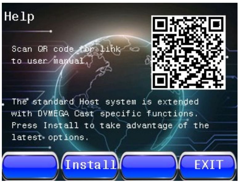
But recently I stumbled across an internet page discussing the virtues of the WPSD PROJECT and when I looked further into this new digital digital voice software suite, I started to see screenshots of the DVMEGA CAST which looked totally unfamiliar to me.
It quickly came to light that I should have updated my firmware on the CAST about 6 months ago! There were really useful benefits available and I had simply been oblivious to them!
One of the bugbears of the old firmware was the start-up times. Most times it would be pretty quick but occasionally it would take forever and go into a loop of restarting. It meant that one had to unplug the power lead from the back, wait a few seconds and then plug it back in. Another little annoyance was that the volume was always set to zero upon start-up. Other than that, I'd been perfectly happy with the unit.
Now that I have V1.32 installed (and the screen firmware has been updated too), the CAST looks like a new product! It switches on virtually INSTANTLY and the volume is set to the default level of your choosing! Worth it just for those two changes.
But there's other benefits too, as you can see from the list in the above image. And when you add to these improvements with the WPSD frontend, it just all feels like someone's given you something for free! 😂💪
So don't be an idiot like me - remember to check your firmware regularly and see whether it's worth updating.
I already thought my DVMEGA CAST was a great little machine, but now I think it's far better. It now has a much more polished feel to it and I look forward to many more great QSO's on it. I know that there are many hams out there who cringe at the thought of using an IP Radio, but for all those people who aren't blessed to be within range of repeaters that do DSTAR, DMR and C4FM, they're a blast! And let's face it, it's not much different to using a handheld into a hotspot is it?
Here's a QSO that I had with K6EGG using the DMC...
After building (and enjoying) a Pocket-Transmatch from Kanga Products in England, I decided to try another one of their kits - the 2W Rooster CW Transceiver. It operates on a fixed 40m frequency of 7.030MHz - the centre of CW activity - but that can be adjusted slightly by swapping out the crystal.
This lovely little kit costs less than £40 and comes with everything you need. Because all the SMD components are already fitted, you only have 20 through-hole parts to install yourself. Kanga reckon that the Pocket Transmatch is their most difficult kit to build, but personally, I found this one to be a little more 'involved'.
First job is to download the excellentBuild Guide from Kanga's website and make sure that your kit has all the right components in the pack. It's always far easier to view the instructions on an iPad or similar tablet rather than printed paper, because when using a tablet you have high-res, full-colour images which you can easily zoom in on.
You'll need a good soldering iron, a multi-meter, a HF receiver, some stereoheadphones (mono will create a short in the audio-circuitry) and a single key (you can use a paddle but obviously only one side will work). You'll also need a 12V supply for the building stage - preferably current-limited (I had a 600mA supply).
I'm not going to repeat the contents of the instructions here because there's just no need - they are extremely clear and concise. The only thing I'd say, is check and double-check everything before moving from one stage to another. And keep your bench clear of all the legs you cut off the components after soldering them.
The kit went together really well and before I knew it, I was ready to do some testing and alignment before the PA transistor is installed. This involved transmitting (yes, without the PA) and then tuning the remote receiver to find the Rooster's signal. I found that my Rooster's output was at 7.296MHz. To cut a long story short, you basically adjust the TX frequency of the Rooster by turning the red trimmer until you get it as close as possible to 7.030MHz. The closest I got was 7.0298MHz.
It does not matter that the Rooster is not exactly on 030 - you put out a CQ and someone will tune into you and away you go. Like I said previously, you can swap out the crystals if you want to change the output, but why bother?
Once I had my alignment done, I installed the PA Transistor, the LED and finished the cabinet. I connected to my regular 13.8V PSU and transmitted a couple of test-calls before looking on the RBN network for any spots. To my pleasure, I was heard by four stations which proved that the little Rooster was crowing 😂
Using a mains psu and headphones (stereo remember), you will note a tiny bit of hum in the audio. It's not bad, but switching to a battery pack reduces it slightly. I would strongly recommend using a 1A QB fuse between the Rooster and the power supply. Remember too that although the power output is low, you still need to feed the radio with an antenna that is pretty resonant or you may blow your finals.
So that's it - nice afternoon project and a nice little pocket transceiver at the end of it.
For size comparison
Specification...
Easy Build 40m Crystal controlled Transceiver
Direct Conversion Design
Part Pre-installed SMD design
Only 20 parts to fit
No coils to wind!
Single Frequency Crystal controlled operation
Front panel RIT control
Approximately 2 Watts RF Output
Active Audio Filter
Pleasant Sinewave CW Sidetone
Visual RX/TX indicator
10-14V DC Operation
Supplied with Strong Aluminium Case
Thanks for visiting the blog. Please leave a comment of just a simple 'hello'.
When I go out to play radio, I usually use a Sotabeams BandHopper II 20/40m Linked Dipole or a BandSpringer Midi EFHW. They both perform really well, but they need height and a lot of space around them, which is not always easy if you're at a popular location.
For a long time I've looked at portable verticals but could never make my mind up - there are so many and it seemed like none of them quite did everything you wanted - or they did, but at an astronomical price - £600 to £700. 😮
Some models have been plagued by reliability problems and quality-control issues. Not the sort of thing you want to hear about when you're lashing out a lot of money! Some designs are super-portable and compact, while others are bulky and a bit of a faff. After spending months casually researching all the options available, I decided that none of them was worth circa £700.
Anyway, as usual, I came across one of my favourite situations - I spotted a virtually new, unused kit at a heavily discounted price and then proceeded to barter until I got it for half-price. I love it when this happens because it ends up being a very safe purchase where I can experiment with the equipment and if it doesn't perform as well as I hoped, I can easily recoup my money. The seller lived in nearby Rochdale, so we met halfway and did the deal.
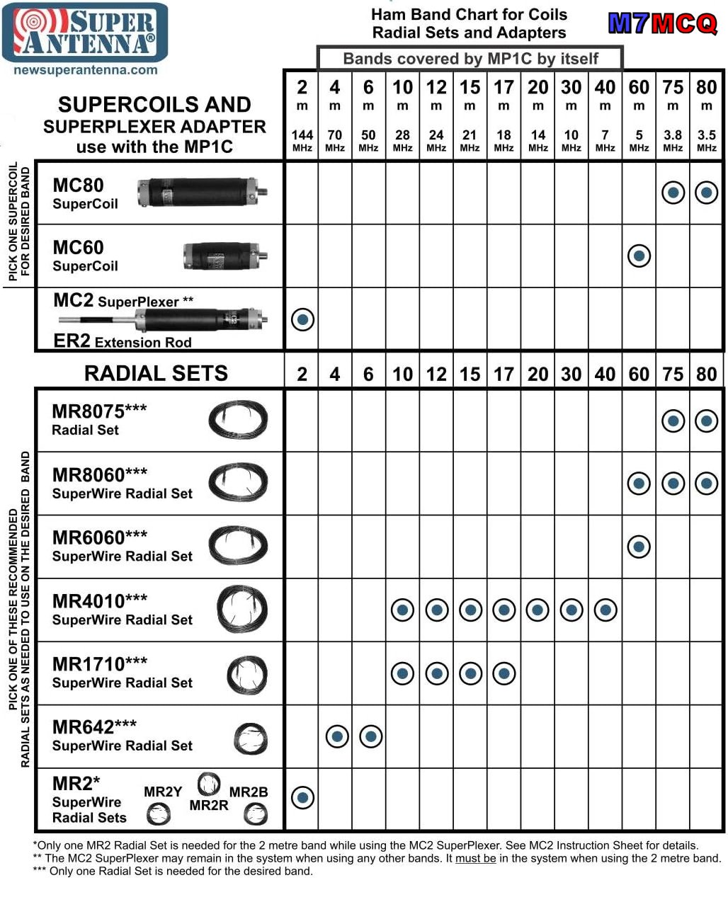
So this time it was in the form of a Super Antenna MP1C LXMAX DELUXE KIT with a SUPERPOD tripod from California, USA. The MP1 is a 1/4 Wave vertical which uses a loaded coil and a set of tuned radials to give you 40, 30, 20, 17, 15, 12, 11, 10, 6 and 4m coverage. In this DELUXE pack, you get another 3 Coilsfor 80m, 60m and 2m with the appropriate radials. Power Rating: 500W SSB, 300W CW/DATA
The stand-out feature of the Super Antenna (apart from its compact dimensions) is the quality of materials and manufacturing. Everything is of a very high standard indeed. This particular model is the very latest incarnation with the model "C" coil and the TM4 tripod, benefitting from over 20 years of development and improvement.
The tripod is light, yet very strong and well made, with a 3/8x16 stud to which you attach the antenna’s UM3 mounting bracket. It’s height adjustable with 3-sections and an extendable centre column, taking the tip of the antenna to around 12ft. The trouble with light tripods is that they’re not particularly stable in high winds, but luckily, the bottom of the centre-column has a hook to which you can attach a weight.
A good alternative to weighing the tripod down would be to guy it off, so I drilled three small holes in the mast head to accommodate this. It's worth doing, because if your tripod was blown over and one (or more) of the coils was smashed against a rock, you'd be gutted!
If you don’t want to carry the tripod around with you, you can opt to use the SP-3 Ground Mounting Spike which makes use of the UM3 SuperMount bracket to quickly setup your vertical on grass or sand, etc.
Normally, the basic MP1 comes with a telescopic whip, but the Deluxe Kit also has Titanium SW1 SUPERWHIP. This 44” whip can be coiled into a 12” circle and stored neatly on the outside of the kit’s Go-Bag as shown in the image below...
So that’s the kit described - how is it deployed?
With the tripod erected (all of 30 seconds), you attach the whip to the top of the MP1C Coil and attach the two aluminium extension legs to the bottom of the MP1C, before fixing it to the tripod bracket. Then attach the appropriate radial-set and lay them across the ground. Some people keep the wires together as one, but I prefer to spread them out around the tripod.
When ready, choose your band and use the handy plastic gauge to determine the height of the loading coil as shown in the image below. It really is very simple and quick. You can fine tune it using your radio’s S-Meter to achieve (usually) a 1:1 reading. Needless to say, your location, height, radials and proximity to nearby objects can affect your readings.
Prior to owning one, I always thought that the plastic gauge would be thin and flimsy, but it's quite thick and strong!
If I’m going to operate on a hillside, I tend not to use the tripod, preferring instead to deploy the SP-3 Ground Spike. With this, the radials start off much lower to the ground, whereas they are raised up five feet when connected to the tripod. I reckon the radials don’t work quite as well when they don’t have that upward slope, but you can still get a very workable SWR.
Sometimes it’s nice to operate from your car/truck (static) and to facilitate that, I have a PL-259-to-3/8 Adapter so that I can fit the MP1 to a regular SO-239 Mag-Mount. This works really well, but I still use the supplied tuned radials. Another option would be to use a PL259-PL259 Coupler between the Mag-Mount and your UM3 Mount (that might actually be better).
Performance : At the end of the day this is a 1/4Wave Vertical - it’s short and can’t (in my opinion) compete with my SotaBeams Dipole, but then my dipole can’t cover 13 bands!! And the vertical’s low angle radiation pattern can sometimes bring surprisingly good DX contacts when the conditions are right.
If you wished to, you could buy an extra MP1C coil and use the antenna in a dipole configuration, but would the improvement be worth the expense? I kinda doubt it. I found a post about this on OH8STN's blog but it all looks a bit long-winded to me.
If you were thinking that this might be an antenna you could use at home indoors or on a balcony, forget it. Under those circumstances you'd be wasting your money - better off buying a loop. If you've got a small garden, that's different - it may work well depending on how built-up the area is and how noisy your neighbourhood is (electrically speaking).
Of course the big downside to using a loaded coil system with a short whip has to be the narrow bandwidth which can make tuning fussy at the 40m end. This is similar to my MagLoop which has very sharp tuning across its range.
I should point out that the MP1 uses a standard 3/8"-24 connector which means that you could experiment with other whips. Many amateurs already have a variety of whips laying around which they've collected over the years and they're very cheap to buy anyway. I plan to experiment with a 17ft telescopic whip that I have. I’m guessing that you won’t have to fully extend the coil if the whip is significantly longer? Mind you, changing the whip means the plastic FG1 tuning gauge becomes redundant. Hmmm, we’ll see how it all pans out.
Operating from a good take-off point (hillside or seaside) and using the supplied tuned radials I found the performance to be really quite good! When using the TM4 tripod, I try to keep the radials off the ground, by using tent-pegs. I have had no problems making Transatlantic contacts on SSB with 5-10W.
Near Winter Hill I quickly setup the antenna at the back of my truck and hurriedly jumped into the comfort of the passenger seat (it was a FREEZING COLD day). Inside the glovebox was the amazing little FX-4CR and I quickly got on-air and started to search for someone to speak to.
Unfortunately, it seemed like everyone was calling for DX, so I had to keep spinning the dial - eventually I found LY2NK who gave me a 55 to start the day. Then I got a 59 from contester S51CK before bagging a few others, including VO1NO from Nova Scotia who has no QRZ log.
Before I froze to death, I managed to contact two Americans - N4LAand W4TJE. They were quite surprised to hear that I was using the little MP1 antenna considering the signal. Below is a clip of the QSO I had with Juha - OH6JJ, showing how well the FX-4CR and MP1 work together…
To a newcomer, these kits may seem a little complex and there are certainly a lot of parts in the Go-Bag, but it's like anything else - you soon get used to it and start to realise that you only need certain parts for certain bands. If you just want to use say 40, 30, 20, 10, then you only need the MPC1 coil and a single set of radials. I keep the relevant coil with the relevant radials, which makes it a doddle to pick the right stuff from the bag without searching around and reading labels. Couldn't be easier!
In this hobby I often find myself looking for ways to improve things and end up fabricating accessories and re-purposing things that make my equipment better in some way, or easier to work with. It feels like the guys at Super Antenna have done most of that for you in this kit - there's a myriad bits and bobs which just make things easy. Having said that, for £700 they could have made it perfect by adding the PL-259 Coupler which I mentioned earlier, the three holes in the mast head for guy-lines and two or three wire-winders.
I love 💚 the idea of 'one antenna covers everything' - just like I love 💚 the idea of a shack-in-a-box like the IC-7100 - I reckon this is a great pairing, since the 7100 is pretty unique in its band coverage. Okay, so the antenna is compromised, but bear in mind that both these items will be used in some of the best locations possible - out in the great outdoors - usually at height!
So in summary, I would heartily recommend this antenna system for anyone who wants a portable antenna which is quick to deploy and doesn't need throw-lines, trees, masts and guy wires. Just stick it in the ground or on a tripod, throw out some radials and use any band you want, including 6m, 4m and 2m.
So what about the elephant in the room - the price? Yeh, that's one big elephant and I can’t imagine why people would spend £700 on this outfit (or any of the others out there). It's an awful lot of money, but then everything in amateur radio is crazy expensive these days. At the end of the day, this is a convenience antenna that you can use in a variety of different situations and locations which might not otherwise permit you to play radio.
Obviously, you don't have to buy the top-end deluxe kit to benefit from this high quality antenna system - you can start with the basic MP1C Coil and whip for around £170 and add extras as you go along.
Am I glad I bought this bundle? For that money, yes!
I found myself wide awake at 5am this morning and so I got up, made a coffee and went into the shack. The room was halfway through being reorganised and so I continued the job for a couple of hours and now it looks all lovely and tidy once again!
Then I went onto Morse Mania and did some CW practise for a while. To be honest, I've been skipping my practise sessions for a few weeks, due to lots of stress at work which makes me feel tired when I get home and not really in the mood for the demands of learning morse.
When I'd done as much practise as I wanted to, I thought I'd connect my key and transmit CQ TEST DE M7MCQ a couple of times on the IC-705 into an EFHW at 5W on 40m. I was surprised to see that my signal travelled across the Atlantic over 4,000 miles.
THAT'S why I will continue to go down this path no matter how long it takes. I'm trying not to beat myself up when I can't be bothered to practise some days - life just gets in the way and I've got to accept that.
I seriously can't wait for retirement! But that's a couple of years away.
When it comes to Antenna Tuning Units, I have the wonderful little Elecraft T1 and the LDG Z-100PLUS. They are both 'automatic' tuners - there is no manual tuning facility - you simply transmit some RF and the units will automatically search for the best match between your antenna and transmitter.
But what if you are using a receiver and can't transmit? Well you're stuck with your mismatch and as a result, your signal may be considerably weaker than it might otherwise be. This is when you would benefit from a manual ATU with knobs and dials. Of course you could use a simple Coupler but then you are limiting yourself to an RX-Only device.
The answer is to find a manual ATU and there are plenty of them available, but I was eager to find a smallone! My first choice would have been an EMTECH ZM-2 but they are ridiculously expensive here in the UK due to the exorbitant shipping costs and the Customs & Excise Duties.
The answer was found right here in England at Kanga Products. They sell a 'Pocket Transmatch' which is small, easy to use and is able to work with both a Transceiver and a Receiver. It is available as a pre-built unit or as a self-build kit (with around 50 components). I chose the latter for £45. It's only a tenner more to have it pre-assembled, which is a bargain, but where's the fun in that? 😂
The kit provides you with everything you need including a rather nice case with printed panels. It measures just 85mm x 55mm and weighs just over 100g. It comes with BNC connectors, covers 80-10M and can handle up to 10W - perfect!!
As its name suggests, this is more than a regular ATU - it's a Transmatch which benefits from introducing some bandpass filtering and is much better than traditional L-Match circuits. The design is made up of two circuits, the first one being a Resistive SWR Bridge and the second part of the circuit is the actual ATU. This device has a switch to permit the use of Balanced and Unbalanced feeds.
This kit comes with fabulous build-instructions but Kanga warn that this is the most difficult kit in their range and I'm guessing they say that because of the toroid which needs winding. A couple of years ago I would have been a little anxious about tackling this, but really, it's a very, very easy process (if a little fiddly).
Winding toroids (especially ones with multiple windings and loops) can be quite daunting to newcomers, but believe me, there's nothing magical or mystical about the process - it's just a case of paying attention to the number of turns and making sure that you're being neat. Taking a photo using your mobile phone and then zooming in to count the turns (and examine for any overlapping) can make the process much easier.
After I built a QRPLABS QDX, I never worried again about winding toroids, so rather than repeat myself here, I suggest that you read through the relevant section of that build for some guidance.
The toroid supplied in this kit is a T68-2 Core and it's not a bad size - meaning that the windings aren't so tight that it'll make your life hell. You basically wind 13 turns, create a short loop, do another 6 turns, create a second loop and then finish off with another 13 turns. That leaves plenty of room on the core.
Next up is to use a separate piece of wire to wind on 7 turns between the existing winding starting 3 turns in. This second piece of wire is coloured differently to make it easy to see what you're doing. The photo below might explain what I mean. Again, this will probably look quite daunting to a newcomer, but honestly, it's quite easy to do and you can always check it again by zooming into a photo of it on your mobile phone.
Once you have the toroid in place, the rest is pretty darn simple - just a case of soldering a few through-hole components. As per the instructions, do not solder the red LED yet. It's important to note that when you fit the two toggle-switches to the PCB, you should not press them all the way down to the PCB - just push the terminals through enough so that you can solder them. If you push them too far down into the PCB, you might not have enough thread sticking through the enclosure's faceplate to fit the retaining nut (although that's only really decorative). Also make doubly sure that the switch is perfectly straight before soldering.
You do have to exercise a little caution when preparing the two variable capacitors because it involves cutting off some of the legs, but if you pause to double-check the instructions, it's a simple process.
Once you've fitted the caps to the front panel and secured with screws, attach some of the insulation tape provided to the back of the caps. This is to prevent anything on the PCB touching the caps. Once that's done, you simply lower the PCB onto the legs of the capacitors. Note that as you are lowering the PCB down, you need to guide the LED into its panel aperture. When you're happy with everything, solder the caps and LED.
The final part is to fit the BNC connectors using the shortest amount of wire that you can manage to work with. Insert the supplied spacer and secure the front panel with the 4 screws. Job done!!
I tested the Pocket Transmatch using an EFHW antenna with my tiny 5W (tr)uSDX transceiver and everything worked perfectly. I might open it back up and adjust the blue sensitivity-trimmer so that the LED goes out completely when the perfect match is found, instead of going very dim.
Size-wise, the ATU is a perfect match for the (tr)uSDX (in fact it's smaller than the radio) and it can easily handle the power (which can sometimes creep up to 7 or 8W depending on the band and the input voltage).
As for operating the ATU, it couldn't be simpler. You flick the toggle from OPER to TUNE, transmit a constant carrier and then turn the dials until the LED goes out (or goes really dim). I tried it numerous times and the dimmest level of the LED matched the best SWR reading on the radio. Perfect! When you've found your match, flick the toggle switch back to OPER and away you go.
Next up was to try it with a receiver, so I connected it to my AOR AR-DV1and (to give it a hard time) my G5RV antenna. I started with both tuning dials to the far left (anti-clockwise) position - I believe that position is close to a 'straight-thru' or 'bypass'. I then tuned into a signal and adjusted the left dial until I heard the most noise and then turned the right dial for the same. Repeating this exercise a couple of times got me the best possible signal and a massive improvement on what I would have otherwise heard.
So this little device is a very worthwhile addition to the shack and I'm really pleased with it. It's tough, compact and can handle all the power I need out in the field. At 80-10M it also has good band coverage. With the enjoyment of kit-building, it's also worth every penny of the £45.