Saturday, 18 December 2021

HANS SUMMERS SUMS IT UP

 I LOVE THIS POST BY HANS SUMMERS OF QRP-LABS…


In the end I think amateur radio is a very broad hobby and this is one of the best things about it, that we should all appreciate the most. Let the CW fan hammer brass and the FT8'er's computers handshake. Bounce signals off the moon, build enormous antennas or a piece of wet spaghetti, a kilowatt or a milli watt. Talk, beep, whisper. Build, buy. Climb a mountain, sail to an island, walk in the park. Whatever takes your fancy! Just live and let live!

Amen!
73, Tom, M7MCQ

Sunday, 12 December 2021

ICOM IC-7610 LOW ON POWER

"MY IC-7610 IS LOW ON POWER"

Yesterday, my friend swapped his FT-DX101D for an IC-7610 and I went over to give him an Interface Lead I'd made, to allow him to connect it to his ATU. While I was there, he noticed that the radio was down on power - and I'm not talking about that "perceived" low power on SSB! 


He was running in RTTY mode to get a constant carrier and tried transmitting at 50W. That produced around 25W. When ramped up to 75W it produced 30W and at 90W it produced around 45W. When he tried to transmit at 100W, the radio reset itself! 😮

After a couple more tests (including a Factory Reset) he rang the seller to inform him of the problem and arranged to take it back.  It was at this point that I suggested that it might be his power-supply, so he swapped over the power leads to another PSU and hey-presto, it worked! 

I only posted this because most beginners wouldn't give their power supply a second thought and would probably end up sending their radio off for repair. It's easy to overlook your PSU when experiencing problems, especially when it appears to be working normally. Oftentimes, you're not even aware that they are malfunctioning and it takes a completely new situation (like installing a new radio) to make you notice a problem that you were previously unaware of.


Anyway, my mate has ordered a new Power Supply and all is well with the world again.

#my radio is low on power
#my icom is low on power
#my ic-7610 is low on power

Friday, 10 December 2021

SAMLEX SEC-1235G PSU

In a corner of the lounge sits my KX3, where sometimes I sit comfortably instead of being in the shack, sat on a stool. Needless to say, I can only really do this when my wife has gone out 😂

Well today was one of those times, so I switched the radio on heard a strong station on 17M and decided to try a contact. At 5W he couldn't quite make out what I was saying so I switched on the PSU to use 10W.

Switching on the Nissei PSU 1230D suddenly produced a huge amount of horrible noise! I checked all the connections were in order and tried again with the same result. The noise raised and lowered in a sweeping pattern and nothing I could do (including altering the voltage-adjuster) made any difference.

The 1230D was a pretty inexpensive PSU but I liked the way it looked and I also appreciated that it had the traditional banana-plug sockets on the front and the more contemporary PowerPoles at the rear. I was quite disappointed to see that it was failing. After digging out the receipt, I discovered that it's two and a half years old.

So when looking for a replacement, I decided to forego all the fancy displays and adjusters and simply put the money into the PSU itself. So on that note, I looked at the Samlex range and opted for the SEC 1235G model which is a 30A PSU with no bells and whistles to distract from the main job of supplying steady, noise-free power.


The Samlex SEC 1235G is about as plain as you can get. It has no LCDs, no LEDs, no knobs, dials, Anderson PowerPoles and no Banana-Plug sockets - just their own power-connectors to which I'll add a pigtail terminated in PowerPoles. 

Of course after finding this PSU, I read reviews and then sought out the cheapest internet price. On Lamco it was a rather hefty £159 but Moonraker were selling it £30 cheaper, so I went with them. 


Much to my surprise, I found that I had built up some credits with Moonraker, so I used the discount and ended up paying just £71 for the Samlex! Happy days 👍
 

I'll report back on the PSU when I've used it for a while. From what I've heard up to now though, they're meant to be a pretty good supply. I'll also open up the Nissei when I get a minute and see if I can find anything obvious at fault.


UPDATE : 

I have modified the Samlex SEC-1235G to include an extra outlet on the front panel. Click the image below for more information....


Wednesday, 8 December 2021

SHERWOOD ENGINEERING TABLE

DOES IT MATTER?

When I started as a licensed operator, I was eager to find some sort of 'benchmark' so that I didn't make a newbie error and buy a duff radio. It didn't take me long to find the Sherwood Engineering Table.


At the time, this seemed like the be-all and end-all, so I gave it much credence and considered it to be more important than the opinions of YouTube reviewers (many of which were financially invested in their suppliers).

Over time I got a little wiser and it was when I purchased a Yaesu FT-DX101D that I realised there was so much more to buying a radio than an RMDR figure from a lab-test!

It made me ask myself a question relating to some older radios I'd either owned or used. The question was simple - did you consider that radio to be a really good receiver??

  • YAESU FT-1000MP Mk5 - Yes!!!
  • YAESU FT-DX3000 - Yes!!!
  • KENWOOD TS-2000 - Yes!!!
  • YAESU FT-891 - Yes!!!
  • Hell, I even consider the tiny BELKA DX to be an absolutely great receiver!
I'm sure that having the 'top-spot' in the Sherwood Table makes for great sales, but it certainly doesn't relate to a great operating experience! I very much disliked the FT-DX101D and ended up going back to an IC-7610.

As far as I was concerned, the two receivers (or should I say four, lol) had nothing between them - they were both superb - it all came down to preferred features and operating methods - and for me, I thought the Icom was the much better radio.

I don't doubt that if you sat down a few operators in front of an FT-1000MP Mk5, they'd be swooning over its superhet sweetness and yet it sits in 107th place in the Sherwood League. 
 

My little KX3 sits 10 places higher than my IC-7610 😮 Is it the better radio? I don't think so, 😂. These are just lab-numbers. Sure, they matter in terms of manufacturers trying to make constant improvements and after all, you can't improve if you don't measure.

But I have now come to realise that the Sherwood Table is not something I should refer to when considering the purchase of a new radio. 

UPDATE
Even though the FT-DX101 is at the top of the Sherwood Table, here's what people have said....

"I've tested extensively, hours and hours, the 101d against the 7610 in the last CQWWCW, in very crowded bands and with all the filters and all sort of conditions, above all comparing side by side very weak signals very near to very strong signals. NO differences at all. 

The 101 could not receive a signal better than 7610. In fact, the 7610 could receive the signals easier, faster, without so many adjustments. Icom 7610 offers much more (best waterfall, better software, more realiability, easier to get good results, better audio, with more bass and smooth, clean, soft sound, LAN, i/q output, play/record, menu system easier, parameters more adjustable , better noise blanker, etc, etc).

ROB SHERWOOD (Sherwood Engineering) 
The FTdx-101D measured better than the IC-7610 on one measurement only, dynamic range because it has a roofing filter.  My three 7610's have never been close to overloading from a local signal let alone a skip signal.

I spent the last two contest weekends (ARRL 160 and 10 meters) doing A/B comparisons between the 7610 and a K4D.  Both are direct sampling and by definition no roofing filters.  The 7610 won hands down on CW and SSB.  Thank goodness modern radios are firmware upgradable for feature improvements and bug fixes. The latest update to the 7610 (and other Icom transceivers) was the new scroll feature. This was a massive improvement for a contester the way the waterfall no longer smears / skews off at an angle when tuning.  

So Rob Sherwood himself has THREE IC-7610's!! I guess that speaks volumes about the value of the table in the "real world".


I recently saw a very sensible post on Groups.IO about this very subject....


Believing the Sherwood Engineering RX Performance List is a list of radios in there rank of performance is false. It is definitely NOT!


It is a list in the order of the radios’ 3rd order dynamic range measurements. (“DR3”)

BEFORE SDR, it was generally OK to consider this also a list in the order of ultimate performance.

Not so today, not by any means!


According to Rob, THE #1 Criteria for choosing a radio is . . . you have to enjoy using the radio.

And THIS is where the RGO-ONE excels!


The early SDR radios (i.e., Flex, with the 5000 being the flagship) topped the list in DR3 performance but their DR3 would fall by 20 dB when used in the presence of other near-by transmitters.   They were very poor radios for use at a multi-TX Field Day site, or a Multi/Multi contesting site.

But for “Home Alone” (i.e., Kevin), they were great radios… if you were OK with a radio having no knobs.


Later radios improved significantly, especially the high end radios.

The problem was overloading of the front-end digital circuitry (i.e., the Analog-to-Digital-Converter or ADC). 


Overcoming this is a two-sided sword.

  • On one hand, the advantage of these new radios is, you could monitor a broad frequency spectrum all at once.
  • On the other hand, to do that, you could not have ham-band specific bandpass filters (BPF’s).


The radios were soon improved in three ways:

1.       Careful gain management, with as little as possible front-end gain before the ADC’s.

2.       By adding switchable BPF’s, one for each ham band . . . or better yet, an analog front end using a Crystal roofing filter, then mixing it to baseband and on to the ADC’s.  But this ‘Hybrid’ front end is very expensive.
 

3.       By using a feature called (among other things) “IP+”, in which a signal is generated within the radio and dithered to the wanted signal. Its effectiveness is dependent on its clock speed and more important, the algorithms used to apply the dither.  There are significant differences in how effective this work from one radio type to the next. 


#1 As you can see from the above, “cheap” can’t get us a good receiver.

#2 does not help improve DR3 measurements because the two signals used are spaced just 2 kHz apart, and are the only signals the radios hear.  This is not indicative of our bands, especially during a contest.


#3 separates the men from the boys.  However, like #2, cannot really be measured in the lab.   We need a very crowded ham band to check this.


As a result, Rob will test all of the high-end radios in at least one major contest, such as CQWW DX, etc.

His evaluation of the radio after using it in a contest is not reflected in lab numbers, nor in his RX Performance List. For this you must read his Full Test Review of each radio.  In it he reports ALL of the lab measurements and then writes a page or 2 or more of comments on how he subjectively evaluated the radio during the contest.


These comments include statements about the ergonomics of the radios.  This includes using the manual controls and the software menus.  Again, there are huge differences in the radios.  They also include comments on audio clarity/distortion.  Rob has said he would not want to use a few of the radios which place high on his list, although he probably won’t say publicly which ones they are.  (‘Your’ mileage may differ.)


Finally:  Dirty Transmitters.  In the past there were huge differences in the different transmitters, and I don’t mean just IMD.  Composite noise is just as important, but it was never measured nor reported.  Since Rob (and others) have begun measuring and reporting this, one company who previously had very dirty transmitters, now has some of the cleanest transmitters available.


Rob’s Info ONLINE:

·       Full Reviews of the Radios:

o   https://www.dj0ip.de/sherwood-forest/sherwood-hf-xcvr-tests/

·       List of transmitters ranked by TX Composite Noise (bottom of page):

o   https://www.dj0ip.de/transceivers/tx-noise/


In summary,  of all of this, the things we like best about the RGO-ONE will be found in the comments of the full-review, not necessarily in the RX Performance List.   This will help spread the word, but only to those who take the time to read the full reviews.

IMO, the RGO-ONE is an outstanding radio for enthusiasts, but will probably never be first choice among those who win contests. … and that’s OK, because most hams have never and will never win a contest!


For now, the RGO-ONE remains an insider-tip.


73 - Rick, DJ0IP

(Nr. Frankfurt, Germany)

May the Sunspots be with Us!


Your comments would be welcome.

2e0fmi

Monday, 6 December 2021

LEARNING PSK ON THE IC-7610

DATA MODES WITHOUT COMPUTERS

Being relatively new to the Amateur Radio hobby, I've never experimented with PSK or RTTY and I thought it was about time that I tried it - after all - experimentation is what this hobby is all about, isn't it??

Thankfully, the ICOM IC-7610 has a built-in Decoder for PSK & RTTY, so no computer is required. At the back of my mind I'd always linked software to operating these data modes and I've always felt that I've got enough on my plate without having to involve computers, software and drivers.


The IC-7610 can operate these modes without any PC involvement and thanks to its ability to connect a keyboard (wired or wireless), it's a doddle to just have a go! 

It was G4ILO's great enthusiasm for the mode which originally got me interested and I was very sad to hear that Julian passed away. Apparently, he'd been battling cancer for quite a while and finally succumbed to it 😢

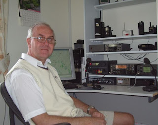
Julian Moss - G4ILO - RIP
 
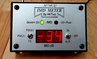
One of the things that I learned straight away from Julian's blog was to take great care not to transmit bad signals on PSK. InterModulation Distortion (IMD) was apparently a huge problem due to poor or careless operators transmitting very distorted signals which would wipe out other operators on the band and make it impossible to decode messages.

Measuring intermodulation distortion of course, is not an easy thing to do unless you have specialised equipment, so most operators just ‘ wing it ’ by dropping their ALC levels and hoping for the best.  Julian chose to invest in a very neat and affordable meter which gave clear indication of your station's IMD - KK7UQ's IMD METER!

These meters are pretty cheap and can be found on the secondhand market for around £50. I got mine on eBay - a bargain. Of course you don't need one of these, but it's good to know that you're running a clean station and not causing interference to others. That is, after all, part of our licensing conditions.

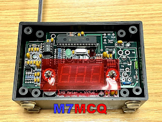
So the IMD Meter is super simple to install - there are no connections to your computer, radio, or even antenna. You just sit it in the shack, raise its built-in telescopic aerial and away you go!


Julian had this to say about the IMD...

"The IMD Meter is an excellent, reasonably priced shack accessory that does a very important job helping you to operate within your license conditions by occupying the minimum necessary bandwidth for the mode, and it could not be simpler to use. I just wish it could be made compulsory that everyone had one of these meters! "

After setup, any transmissions with unacceptable levels of distortion will result in a warning light, and audible tone and an informative readout on the display. It also has a Field Strength mode, so you can use it to sniff out RF in your shack or anywhere else. Now onto the actual operating procedures...

It's always difficult to go into a new mode of operating when you're brand new to the game. The very last thing I wanted to do (apart from transmit noisy signals) was to interrupt other people, annoy them with my rookie attempts and get flamed!

So I looked around the internet for some tips on how to start. Thankfully, there's some great advice out there for learning both PSK and RTTY.  It seems that PSK can be more of a chat environment, whereas RTTY appears to be made up of brief 599/73 type activity.  I might be wrong there, but that was my initial impression, so I might end up coming back here editing this paragraph, 😂. In any case, I don’t think there’s a great deal of RTTY activity these days.

Anyway, I decided to start with PSK and the first thing to do was find out where the signals are to be found on the bands, so a quick trip to the RSGB BandPlans revealed the correct part of the spectrum to be tuning into for the digibands.

With the correct frequency range tuned in and the IC-7610’s decoder switched on (it’s visible in the Menu once you’re in PSK Mode), I started to watch the messages going backwards and forwards. It all seemed a little confusing at first and I wasn’t sure at which point I would be CQing or responding to a CQ. So I watched for a while and followed other people’s interactions and did my best to learn about the best operating practises in this mode.

So I started with the 20M band because that's where my EFHW antenna is most efficient. Tuning into 14.070.150 brought in a stream of messages between operators and it allowed me to get an idea of how people were using PSK and what sort of exchanges were favoured.

Following particular individuals, it soon became apparent that some operators liked to 'chinwag' just like on SSB, while others were less keen on that and simply wanted a short exchange for the log.

The IMD Meter showed that my transmissions were perfectly clean at -34dB which makes you feel good that you're not splattering the band with distorted signals.

The other thing I'd have to learn about is all the abbreviations! I'm obviously familiar with most, but some I had to look up like KN and OM. My overall lack of knowledge of this mode led me to start off by responding to CQ's rather than me calling CQ. I usually do the same in FT8.

It's been a very enjoyable start to learning to use PSK and (like FT8,etc)  I'm sure it's going to be a regular mode of operation when the bands are quiet on SSB phone.

Common operating frequencies...

Amateur BandUSB Dial Frequency
160 metres

80 metres

40 metres

30 metres

20 metres

17 metres

15 metres

12 metres

10 metres

1838.150 kHz

3580.150 kHz

7040 kHz and up

10142.150 kHz

14070.150 kHz

18100.150 kHz

21080.150 kHz

24920.150 kHz

28120.150 kHz

If you're a newly licensed operator and have never tried PSK, give it a go! It can be fun.

73, Tom, M7MCQ.

Thursday, 2 December 2021

RURAL RADIO SILENCE

PLAYING IN THE TROUGH

In the last 3 months I've felt under a great deal of pressure at work and haven't had a day off (or even an hour) in the last 3 months! At weekends I've just felt too knackered or stressed to go out and relax.

So I eventually managed to get a couple of days off to get my head out of the work-pit. Thursday, Friday, Saturday and Sunday all to myself and considering the weather was unusually bright today, I decided to grab my rucksack and go for a walk in the TROUGH OF BOWLAND which is just under an hour away from my home.


It's a beautiful place which I know very well because I have a holiday home just around the corner from it. Because it's Winter and the days are short, I couldn't go to some of my preferred (higher) locations, so I had to stay relatively low.

If you've never walked around the Forest of Bowland, you really must do something to change that - it's a stunning place, offering something for everyone, including families with kids. Needless to say, it's great for dogs too, but they must be kept on a leash - there's lots of wildlife and livestock around.


After stopping for a hot drink and breakfast sandwich at a well known Chuck Wagon in the Trough, I started my walk and pretty soon I was setting up my station which consisted of the ICOM IC-705 and a SotaBeams EFHW with counterpoise. I also had an Elecraft T1 ATU with me.


By the time I got set up, it was incredibly cold and there was a steady wind that kept the temperature low. Brrrrrrr! Of course, like an idiot, I forgot my gloves, so it was all very uncomfortable.

Switching on the radio warmed my heart though, because the noise level was on the floor. Almost silence!! Spinning the dial found loud, clear signals straight away. They weren't particularly strong, but boy, were they clear. I made SSB contacts all over Europe, Russia, and Canada. I was going to play some FT8 but my fingers were FREEZING! So after a couple of hours I closed shop and headed back home with heated seats on the highest setting 😂

Had a fabulous day and it was much needed!

Thanks for visiting.

73, Tom, M7MCQ.

Saturday, 27 November 2021

QRP-LABS QDX KIT (BUILD)

A BEGINNER
BUILDING THE QDX KIT

When the QRP-Labs website went live with the sale of the long awaited QDX, I was there, mouse in hand waiting to add one to the Shopping Cart, but to my amazement, the Cart told me that the product was Out Of Stock even though it had only just come online! I believe they had around 400 units and they all sold immediately. I was gutted!


To make matters worse, one of the chips on the PCB were no longer readily available, so QRP-Labs would have to try and source an alternative before they could get some more QDX's manufactured - and how long would that take?? Some people were saying that it could be months 😓

Two of my radio-club friends had been fortunate to have secured their purchase and it wasn't long before the kits dropped through their letterbox. In no time at all, one of them built his and had it up and running. The other guy decided he simply had too many things going on to build his kit - and sold it to me - hooray!! 

I was so pleased about this because I really fancied not just the product, but the building of the kit too. I'd previously built a little Transistor Radio Kit by Tecsun and found it to be a great little weekend project. The idea of building something a bit more technical (not to mention more useful) was very appealing.

So I will use this post as a brief BUILD LOG. I'm not going to go into every detail because there's some excellent Video Logs on YouTube which are far more advanced than anything I could ever do. My take on things will be about how easy (or not) the kit is to build from a beginners point of view. 

I'll highlight any hurdles and point out any pitfalls. I might even end up pointing out how everything went pear-shaped 😂😂😂. Fingers crossed it goes well.

_____________________________


The manual for the QRP-Labs QDX Kit is a staggering 105 pages long but only the first 37 pages are related to the actual build. Following that is a really good section guiding you into the actual operation of the QDX with software such as WSJT-X. The remainder of the manual goes into great detail about the design of the product, which was way over my head!


After checking the inventory to make sure you have all the parts available in the kit, the build is split into 14 sections and starts with the installation of the ceramic capacitors. Each part of the build looks quite straightforward but I must admit to being a little apprehensive about winding all those toroids for the Transformer, Inductors and Filters. Something I've never done!


NOTE : THE FOLLOWING SECTION relating to 4 inductors no longer applies to new versions of the QDX! 

There's one other part that I'm really nervous about 😕and that's the task of removing four Surface Mount Devices which QRP-Labs discovered were causing problems in the HF region due to self-resonances (after manufacture). These four miniscule inductors have to be physically removed (by desoldering) and replaced with four new ones supplied in the kit. The tiny pads on which the SMD's sit, are incredibly easy to damage 😬.  To be totally frank, I was really disappointed to learn of this problem and I believe QRP-Labs should have made it very clear that the end-user had to tackle a job which would not normally be expected in kits of this nature. SMD stuff is very tricky to handle!

The replacement parts are thru-hole components. It would be a real challenge for a beginner like me to work at SMD level, so I opted to get a friend (G4HYG of Cross Country Wireless) to do it for me so that I could relax and enjoy the rest of the kit. 
 
Chris is a professional constructor of radio equipment and told me that he considers this QDX unit to be for Advanced builders because of the toroids, let alone the SMD work! He advised me to make the whole kit and then pass it to him to remove the 4 SMD inductors and run a Lab test to make sure I'd done everything right.

Looking around in the various forums and groups, I could see that quite a few people were having issues with failed output transistors and even the total death of the QDX. Reading between the lines, I could see that some of these failures might be attributed to the constructors choosing high input-voltage. Many people wanted the convenience of being able to use their standard 13.8V supplies and this results in a much higher power output than is recommended (potentially up to 8W), so I decided to go for the standard 9V input with up to 5W. 

So, onto the kit. Well the first thing that smacks you in the face is the minute sizes involved! In the past I’ve built a small transistor radio kit and that was pretty compact, but the big difference here is the toroids - they’re absolutely tiny!!

5pence piece!!

 
I’d been watching some videos of people winding these things but hadn’t really noticed their diminutive dimensions, probably because they had been using a large magnifier. Well now I can see them in the flesh and I’m more anxious than before 😂😂😂

Anyway, I’m going to follow the Manual to the letter and that starts with fitting the Capacitors, followed by the Diodes, Transistors and then the TCXO board. After fitting anything I recommend ticking it off in the manual. Same goes for any testing that you're asked to do. Tick it off and you'll not miss anything.


With that done. it's time to do the T1 Transformer. I wasn't 100% confident with this but hopefully I've done it right 🙅


According to the manual, the next step is the Tapped Inductor L12, 

BUT STOP FOR A MOMENT!! 

If you are a beginner to all this kit-building and in particular, winding toroids, I would strongly advise you to hold back on the L12 for a few minutes and pre-build the other toroids, L14, L2, L3, L4, L6, L7 and L10.

Why?? Because these other toroids are super simple to wind and it will be good practise before starting L12, which has 3 loops in it (taps) and it's easy to get things wrong (like I initially did).

DO NOT INSTALL the other toroids, but just build them up ready for use later and be sure to mark them with a bit of masking tape before putting them aside.


You can see in the above example (L10) that this toroid has 13 turns as counted from the CENTRE. The "FIRST TURN" is the one on the right and it is counted anti-clockwise. 

Okay, so now that you're much more comfortable winding toroids, you can start the bigger L12 feeling like you've got some experience behind you. The only difference here is that you will need to put three loops in at varying points in the winding process. I would recommend watching a video by someone called MISCDOTGEEK.

Remember to count your turns VERY VERY carefully! And remember too, that the loop goes BETWEEN the turn-numbers mentioned in the manual, so for example, as you have just completed turn 19, form a loop and then carry on with turn 20. The loop itself is not a turn!

Below is a simple example I've made up showing how a 6-TURN toroid with a Tap between 3 & 4 would look. Note how the winding starts on the left at the TOP of the toroid and ends at the bottom.


I'd like to give you a couple of tips... When you've wound the L12 Tapped Inductor and are feeling proud of yourself because you've checked it over and over and are 100% confident that it's perfect, just stop a minute and do yourself a BIG favour!

Get a Hot-Glue Gun and neatly fill the centre of the donut and give it a few minutes to cool. This will prevent the wire turns moving around as you wrestle with the toroid as you try to get all 5 termination points into the holes on the PCB. Without this, it is incredibly easy to get wires crossed over and out of alignment (I'm speaking from experience)!

It's still easy to get movement of wires on the outside of the toroid, but at least you don't have to worry about the inside wires.  When you've finished the L12 Inductor, carry on following the manual - including the continuity tests on Pg.24.

The second tip is to forget the advice in the manual about burning off the enamel with your soldering iron or using the side-cutter method. No disrespect, but beginners are very likely to do some damage with either method in my opinion. It's better to scrape the enamel off with a sharp scalpel. 

The next toroid to do is the T2 Trifilar which is super simple but you need to twist 3 lengths of wire together as one before doing the winding. The manual suggests using a couple of little screwdrivers to do the twisting but believe me, it's far easier to use a small, variable-speed drill. Put one end of the three wires into the drill-chuck and hold the other end of the wires taught with a pair of pliers and then SLOWLY rotate the drill. Make sure there's a nice neat row of twists and no kinks! 


With all the toroids installed, I would suggest using the Hot Glue Gun to help keep them all in place. Without it, they'll be quite wobbly and prone to possible damage from knocks (even when in the case).


That's it! All the other components are very simple to install and are well within the capabilities of a beginner (if you pay close attention to the information in the manual). Needless to say, the replacement of the SMD Inductors is ridiculously difficult for a beginner, so you should either seek professional help as I did, or wait for the second batch of kits which will have the correct inductors pre-installed (and the TXCO). The new versions (ie. above Ver.1) do not need this mod, so don’t worry!

UPDATE : Chris G4HYG  replaced the tiny inductors and a few minutes ago I collected it from him. He had put the radio through its paces in his Lab and it was pushing out a solid 5W on all bands!

He also tested it in action on FT8 and reported that the 30M band sensitivity seemed slightly low but he still managed to make contacts as far away as Kazakhstan, so it's not that bad! He said it was a "Little DX machine". So my thanks to Chris for doing the SMD bits and the testing. He also tested the unit on 60M but that's a band I'm not allowed to use as an M7.


All that was left to do now was to fit the unit into its box and screw it together. Just in case the transistors started to get hot with lengthy FT8 use, I drilled a set of ventilation holes in the case, top and bottom. I very much doubt that they're going to be needed, but it costs nothing to ventilate the box does it? 


REAL LIFE RESULTS:

As a real measure of the QDX, I decided to connect it to my SotaBeams BandHopper which I'd temporarily installed in the back garden. It was setup in 40M mode which was just as well because I can only test during the evening times due to work commitments. 

Although the BandHopper is supposedly resonant on 40M, the SWR is still slightly higher than I'd like down at 7.074MHz so I put the Elecraft T1 ATU inline to fine-tune the antenna and give the little transceiver an easy time.

I plan to try it on an indoor Magnetic Loop later and I'll have to pre-tune the loop using another radio (probably the IC-705) to make sure it's spot on before connecting the QDX to it.

To power the radio, I used a battery which I'd purchased specifically for the QDX. It's a 7.4V Lipo with a 5,000mAh rating. That should give me a good few hours use out in the field! For home use I've got a small mains 2A PSU putting out 9V. I was pleased to see that the PSU added no noise.

7.4V LIPO

Setting up the QDX for WSJT-X was pretty straightforward and there's more than enough information in the User Manual to guide you through it if you've never used the software before. The only thing I don't like about this transceiver is that you can't reduce the power output - not even by using the Power-Slider in WSJT-X. That's a shame really, because I'd have liked to have the option to drop power right down into the mW range for experimenting with antennas and such like.


I've wrote a post on the QRP-Labs User Group to see if anyone can suggest why my receive signal seems down and hopefully they can make a suggestion as to why it may be so and how I can improve it.

Anyway, I'm just impressed that it even works! 😂😂😂

I'll update again later.

73, Tom, M7MCQ.


UPDATE : I reheated the solder points on L12 and the receive signals are now at normal levels but 30M remains slightly low. Nevertheless, contacts can still be made on that band (although I rarely use it to be honest). 20 & 40 are my favourite bands for FT8 👍 


UPDATE : I built a very handy little SWR BRIDGE to protect the QDX finals from any high levels of reflected power during the "tune-up" procedure. It's a fantastic kit and incredibly easy to build. Click HERE to see more details.