
IC-7300 MK2 MINI-REVIEW
Having got shut of my Yaesu FTX-1 🙏, I made the (very easy) decision to keep on using the wonderful IC-705 for outdoor use and to add the new 7300-II to the shack. And you know what? It feels great!!

As much as I really wanted to love the FTX-1 Optima, I found myself increasingly disappointed with it. Despite losing money 🙄 I was still excited to just put it behind me and get back to enjoying radio!
I had a 7300 a few years ago and it was a great radio but the Mk-II has just made things even better. That’s what you want from a new model - new features and improved function - are you listening Yaesu??
Icom have sold over 100,000 Mk1’s, making it one of the most popular and influential transceivers of all time. When introduced to the UK market (almost a decade ago), it was a genuine game-changer, bringing high-end SDR tech at entry-level prices, setting new standards. It left everyone else in this sector of the market trailing behind for the next few years.
Apart from being a fabulous budget-priced 100W HF, 6M & 4M SDR transceiver with built-in ATU, it was also compact enough to be used outdoors and the 4.3” colour TFT touch-screen was perfectly visible in bright sunlight - as a result you’d often find it used for Field Days and POTA activations.
So what does the MkII bring to the table? Well of course it has all the benefits of the original version plus a few improvements…
- An improved receiver! The old one was great anyway, but improvements are always welcome. The RMDR has been increased to 105dB for a better dynamic range.
- Improved TX Phase Noise! A 12db improvement - now -139dBc/Hz @ 1kHz.
- Improved Power Consumption! Radio only draws 700mA in standby.
- Cooler Operating Temp! I never thought the old one ran hot, but cooler is good.
- USB-C Conector! Much better than the old USB. AND it provides two com-ports!
- LAN Connector! This makes Remote Control far, far simpler! Inline with the 7610 RC.
- RX-In/RX-Out! So pleased to see this valuable addition.
- CW Decoder! So now the 7300- can decode RTTY and CW.
- HDMI Port! External big-screen display.
- IPS SCREEN! IPS replaces TFT for better detail and colours
So all in all, a very nice collection of useful upgrades! And no losses. Thank you Icom for listening to your customer-base and giving them what they want.
Looking at the front panel there’s virtually no changes apart from the colour of the Power Switch and the ‘Mk2’ logo. On the back panel however, it looks significantly different…

Having extremely limited space in the shack means that the compact 7300 is a perfect fit, but the downside is that I have to locate the radio to the left of my sitting position. To be fair, that’s not really a problem, since I’m one of those people who prefers to operate their base station via their computer most of the time and that allows me to use my PC’s 32” curved screen, amplified speakers and my Elgato Wave 3 microphone.


To be honest, I didn’t have access to a LAN port in the shack, so I bought a WiFi Extender which includes an RJ45 LAN port and plugged it in nearby. It works superbly and was an absolute doddle to setup! It has also boosted the performance of my computer’s built-in WiFi, making downloads much faster than they had been previously. And best of all, I paid for it with some Amazon Gift Vouchers that I’d received for my (67th) birthday. Result!!
It’ll probably come as a surprise to hear that I didn’t bother using the HDMI port at all 😮. To me, it’s little more than a vanity screen and is only of any real use to the visually-impaired.
With all the basics connected, I powered up and checked that everything was working properly. I heard IX1HPN on 20M and gave him a shout at 10W. He had a pile-up going and I struggled to get through so I increased power to 25W and still struggled, thanks to my extremely compromised ground-mounted vertical antenna 😢. After repeated attempts, he finally heard me and gave me what he called a genuine 59+.
The Mk2 receiver didn’t sound any different to the last one I’d owned. It didn’t sound any better than my 705 or the Yaesu FTX-1. In fact, I believe that most modern SDR receivers sound pretty much the same and I’m convinced that 9 out of 10 operators who attach such great value to the Sherwood Table would come unstuck in a blind listening test!
 |
| IC-7300 Mk2 with my 5yr old IC-705❤️ |
The Noise Reduction on the 7300 doesn’t offer anything ground-breaking and that’s always annoying to me when I witness the absolute wonders of the NR2 on the cheap Hermes Lite II - nothing comes close to it! But, it is what it is and I find most of my noise-reduction success comes from making regular use of that little RF GAIN dial!
A mate of mine (M7XCA) reckons the Mk2 pulls in a fraction more noise than his Mk1, but maybe that's because his old Mk1 is a little less sensitive than it used to be. It’s hard for me to comment right now because I’m absolutely surrounded by Xmas lights, Xmas trees, Xmas animated decorations. I sure do wish I had no neighbours! 😂
The old 7300 screen was a TFT and that has been updated with an IPS screen, offering better colours and better performance in bright light. The difference isn’t huge, but it’s definitely an upgrade. Whether it’s more durable and longer lasting than the TFT is a question with no answer. All I can say is I hope it’s better than that crappy screen on my Yaesu FT3D🤬.
The new CW Decoder works extremely well and I found that the AUTO mode does a fabulous job of determining the speed and decoding accurately (with a clean signal).

Knowing that everything was working well, I downloaded the latest drivers from Icom’s website and then plugged in the USB cable to the PC. With that done, it was time to install the RS-BA1 Remote Control software and connect the lovely RC-28 external VFO Dial.


Once I’d got that running (I had to update the software to get it to recognise the 7300Mk2), I started to focus on installing an SDRPLAY RSPA1 receiver.
Originally, I thought that I could just plug my SDRPLAY into the 7300’s RX out, because that’s what everyone was saying on the YouTube (and even at Dealerships) but when I did, I got nothing! You need to “activate” the RX antenna ports by switching RX-ANT on in the Function menu. The trouble with that is, you’re 7300 will then stop receiving and the radio’s panadapter will go dark.
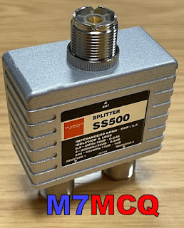
And then I recalled a similar experience with my IC-7610, where you need to place the external receiver into a loop using a splitter. I've created a diagram showing how to connect it...

By using a decent quality splitter such as a Mini-Circuits ZCS-2-2+ or a Diamond SS-500, you can be assured that you are also providing a good degree of isolation between your transceiver's receiver(s) and the external receiver. Typically, you're talking about more than 30dB isolation, so there's very little chance of interference from one receiver to another.
At the time of purchase, the Mini-Circuits splitter wasn't available anywhere in the UK - fresh stock wasn't expected for another 3 months, so I turned to the Diamond SS-500 which is well made but at £70 is quite expensive and has an insertion loss of 0.8dB. The Mini-Circuits device has a lower (0.4dB) insertion loss, but costs around £90. As usual in these post Covid times, stock shortages pushes prices up to ridiculous levels, and you have to choose between stumping up the cash or waiting months. I chose the former.
Before I could install the splitter, I needed to make up some PL259-to-SMA patch leads using short lengths of RG-316. Once that was done, I connected them all up.
I then loaded the latest version of SDRuno along with all the various add-ons and also made sure that OmniRig was running and configured for the IC-7300.
With everything setup correctly I switched on the radio and ran SDRuno. The two interfaced perfectly and it was good to see the full layout and tools of SDRuno.
Version 1.4.2.1710 is the latest version of SDRuno at the time of writing and is incredibly rich in features. There are a couple of bugs, but the software writers are fully aware of them and are working hard to sort them out. I’m also going to install SDR-CONNECT V1.05 too, along with SDR-CONSOLE...

Anyway, the V.1.4.2 software ran perfectly and it feels good to have SDRuno back on screen, especially this latest version which allows you to have up to 16 virtual receivers running at the same time!! Things have changed significantly since the last time I connected an RSP to a radio and I'm looking forward to exploring and experimenting.
PLEASE NOTE> Once you’ve made these connections, you need to switch the Receive Antenna option on which can be found on Page-2 of the FUNCTION MENU. I’ve actually assigned the RX-ANT function to the VOX button for quick access. Please note further(!) that whenever you use a splitter (no matter how good it is), you will lose a small amount of signal, so if you wish to avoid this, you can use an SDR Switch instead such as this one from ML&S.
Needless to say, you cannot use this Splitter method if you also want to add an external RX antenna such as a LOTG. You'd have to use the more traditional method of an antenna switch such as the MFJ-1708B, etc.

BEAR IN MIND that you don’t need an antenna splitter or an antenna switch if you’re happy to just use your external SDR for listening to your signals - just connect your SDR to the RX-OUT port, switch on the RX-ANT and away you go.
The final step of the 7300 installation was to configure it to communicate with the SUPERB remote-control app called SDR CONTROL FOR ICOM. I have used this with my 7610 and 705 using my IPad and it works flawlessly!! It’s simply the best RC software out there if you have an IPad.


So that's it for now. Everything is working very well and it's time to sit back and just enjoy playing radio without all the buggy distractions that the FTX-1 brought. Happy days - thank you Icom!
I'll post more after a couple of months use.
73, Tom, M7MCQ.
.


