Saturday, 19 February 2022

LDG MC-7610 REVIEW

EXTERNAL ANALOGUE METERS

Who doesn't like big analogue meters?? No one! There's just something a little magical about them and when I am using the Icom IC-7610, I love to switch to the big VU-style meters on the display but then I lose my expanded scope and waterfall.

The answer of course, is to use an external meter and thankfully, LDG have made a unit containing two analogue meters in a single steel case. There's one meter for each receiver in the IC-7610 and they can be set to indicate Signal Strength, Power, SWR, ALC, Compression, Current or Voltage.


Straight from the box, the LDG MC-7610 looks pretty impressive. It looks and feels like a quality bit of kit, unlike some of the MFJ meters I've seen (and owned). Each meter measures around 75mm wide by 35mm tall and the case itself is 220mm x 85mm x 85mm (WxHxD). There are four feet which add another 5mm to the height.

The meters are illuminated and have adjustment on the rear panel for individual brightness and colour. Also at the back is a Power Button, a Power Connector (12V+/- 15%) and a Radio Interface socket. The supplied interface lead is a simple 3.5mm stereo jack-plug to jack-plug. It's rather short, so unless you're planning to sit the meters right on top of the radio, you'll want to buy a longer lead.

Strangely enough, the meters don't work unless you supply the unit with power. I thought that the power connector was for illumination purposes alone, but it's not.

I strongly suspect that these meters will work perfectly well with the IC-7600 and maybe even with some other dual-receiver Icoms that have the external-meter connect. You can see on a close-up of the meter itself, the word M-7600.


So apart from looking fabulous, what do these meters offer ? They give you a nice easy to read meter for each receiver and permit you to place them in a location which suits you. They cost around £190 new I believe.


Am I happy with the purchase? Yes, for sure! They look so cool and are really easy to read from my operating position without the need to reach for my glasses. 

Thanks for visiting the blog!

73, Tom, M7MCQ.

Friday, 18 February 2022

KENWOOD TH-F7E Mini-Review

GOLDEN OLDIE
A 'USED' HT BARGAIN!


If you're on the hunt for a very cheap, value-for-money handheld transceiver, you'd do well to consider the discontinued  KENWOOD TH-F7E. Of course there's lots of HT's out there on the second hand market, but the feature which makes the F7 stand out from the crowd (apart from its low price) is its wideband rx and its ability to receive HF SSB!

The radio is an FM DualBand 2M/70cm transceiver with a 5W output. It's capable of listening to two separate frequencies at the same time (even on the same band). The ultra-wideband receiver has a wide range of modes including AM/FM/FM-N/FM-W/SSB and even CW!

There's also a wide range of tuning-steps including a very fine step for accurate SSB tuning. Inside the unit is a ferrite-bar for AM Broadcast listening - something which is often omitted in other handheld radios of this type. The only other HT I've owned with a built-in ferrite antenna was the Kenwood D74 (which cost me an arm and a leg).

With two bands available (Main-A and Sub-B), you can monitor any two frequencies of your choice, or if you prefer, you can de-clutter the screen and just have one band active. The Main-A band provides full TX/RX on VHF and UHF, while Sub-B provides RX only from 0.1~1300MHz in any mode.

In addition to the 'rubber duck' and ferrite antennas, Kenwood have made provision for an external antenna to be fitted which makes it very convenient to throw a long wire into a tree and massively improve your SWL capabilities.

Needless to say, this old-timer does not offer any digital modes, so if you're looking for some action in the DSTAR/C4FM/DMR fields, dig deeper into your wallet!

The real beauty of this radio to me is its size and durability. It's tiny and it's tough! And that means it's going to go with you much more often than a bigger radio - especially because it's got such a wideband RX. Okay, so it won't win any awards for selectivity or sensitivity, but if you're out and about up in the hills, it's perfectly adequate and more so with a simple wire connected to it. The radio also suffers from some birdies and these are actually mentioned in the manual. But all in all, it's a great little receiver - especially for this amount of money.

I walked the dog the other day and slipped the F7 into my pocket. I also took a small retractable wire antenna. I knew there was a competition going on and once on top of Winter Hill (just a couple of miles from my home), I threw out my wire into a nearby bush and heard scores of loud, clear stations from all over Europe, Asia and even America on SSB. I could also detect weaker signals but it was much harder work deciphering what they were saying, especially with their accents and the pileups and qsb.

The radio benefits from really good construction methods and it feels incredibly tough (MIL-STD 810 C/D/E) - you certainly don't fuss over it like you might do with other radios. It's also showerproof which is a great thing when you're out and about walking. All the buttons have a very positive feel to them and the Multi-Scroll key makes easy work of the menu system. The only negative here is that there's no illumination for the buttons. The internals of this little marvel are regularly applauded by technicians for the very high quality design and manufacture.  "This ain't no Baofeng" 😂

As usual from a Kenwood radio, the audio from the small speaker is pretty darned amazing. I just wish that other manufacturers would learn from Kenwood in this respect. My Elecraft KX3 for example has terrible audio from the loudspeaker and they simply advise you to use a headset instead and to treat the speaker as an emergency backup! That's ridiculous when you see how well Kenwoods sound - even at this diminutive size.

Battery life (1500mAh)?? Well it's pretty good actually. Even though it's not like the modern batteries of today, it really does surprise you how long it lasts, so much so that I'm not even thinking about searching for battery options.

Finally, this radio has over 400 Memories available for programming and with its fast scan-speed and wide coverage, it makes an excellent Scanner too! Scanning the AirBand produced good results but I would say not quite as good as a dedicated AirBand receiver. Still, most people would be using an AirBand scanner at and Air Show or close to an airport and in those circumstances, it performs flawlessly.

I bought my first TH-F7E from eBay for the princely sum of £75 including carriage. It came with all the original bits and bats, manual and even the original box. 

So there you have it. An excellent little radio for the Radio Ham or the SWL.


Specifications

* 144 - 146MHz Tx/Rx: FM 

* 430 - 440MHz Tx/Rx: FM

* 0.1-1300MHz Rx: FM-N, FM-W, CW, SSB, AM

* Memories 434 

* Large Frequency Display

* 5W HI, LOW, EL 

* Internal VOX

* Automatic simplex checker 

* Memory shift

* Time-out Timer & APO

* 16 button key pad plus multi-scroll key

* Internal bar antenna for MW AM broadcasts

* Special charging/operating circuit

* Lithium-ion battery pack 7.4V/1550mAh

* 58 x 87 x 30mm * 250g


UPDATE FEB 2023

I have since sent this transceiver to a special Overseas Appeal 💗

73, Tom, M7MCQ.

Leave a comment below if you have experience of the F7...


Thursday, 10 February 2022

IC-7610 WATCH

APPLE WATCH & IC-7610

Wouldn't it be nice if you could control your ICOM IC-7610 from your watch? Well that's unlikely to happen for quite some years, lol, but in the meantime you can kid you mates and have this fabulous animated watch face on your Apple Watch!

It has a swinging s-meter and an animated waterfall. How cool's that??

It comes from an app called CLOCKOLOGY which provides amazing watch faces and allows a high degree of customisation too. Costs £1.79pm. I'm not advertising - I'm just putting the info here that I know I'll be asked for.

73, Tom, M7MCQ.


Thursday, 3 February 2022

DIAMOND SS-500 & RSP1A

Connecting your SDRPLAY to your IC-7610

With previous radios, I have shared the antenna with my SDRPLAY device via an MFJ-1708B which has certainly worked, but it's messy and you never feel 100% convinced that it's going to protect the front-end of your external receiver. The best way to protect it is to not put it in harms way in the first place and you can do that if your radio has a suitable connector. Some transceivers (like the FT-DX3000) have a very simple RF-OUT connector which means that you just plug your external receiver into that connector and hey presto, it works.

The Icom IC-7610 has a different arrangement. It has RX-IN/RX-OUT BNC sockets on the back which form an RX loop, allowing you to insert a receiver inline. This means that you are never putting your SDRPLAY (or whichever receiver you use) at risk. I thought originally that I could just plug my SDRPLAY into the 7610's RX out, but when I did, I got nothing!  Apparently, you need to place the external receiver into the loop using a splitter (see the diagram that I sketched above).

Why Icom chose this method over the simpler one employed by Yaesu on the FT-DX3000, I have no idea. Presumably there's a benefit or it's due to the fact that the IC-7610 has Dual Receivers and very comprehensive antenna switching capabilities - I don't know.

By using a high quality splitter such as a Mini-Circuits ZCS-2-2+ or a Diamond SS-500, you can be assured that you are also providing a good degree of isolation between your transceiver's receiver(s) and the external receiver. Typically, you're talking about more than 30dB isolation, so there's very little chance of interference from one receiver to another.

At the time of purchase, the Mini-Circuits splitter wasn't available anywhere in the UK - fresh stock wasn't expected for another 3 months, so I turned to the Diamond SS-500 which is beautifully made but at £80 is horribly expensive. The Mini-Circuits device cost around £60.  As usual in these Covid times, stock shortages pushes prices up to ridiculous levels, and you have to choose between stumping up the cash or waiting months. I chose the former.

Although the price was higher than those retailers who had no stock 😲 RadioWorld were quick to deliver - it arrived the very next morning and was well packaged. 

The Diamond SS-500 is good from 0.5MHz up to 500MHz which falls way short of the SDRPLAY's frequency range, but that's of no consequence to me, since I'm only interested in HF coverage. 

Before I could install the splitter, I needed to make up some BNC-PL259 coax leads and a PL259-SMA lead. Once that was done, I somehow managed to connect them all up without pulling out the IC-7610 from its tight-fitting place on the shelf - miracle!!

I then loaded the latest version of SDRuno along with all the various add-ons and also made sure that OmniRig was running and configured for the IC-7610. 

With everything setup correctly I switched on the radio and ran RSDRuno. The two interfaced perfectly and it was good to see the full layout and tools of SDRuno instead of the very limited EXTIO version which I'd tried previously with limited success.

Version 1.4.1.1 is the latest version of SDRuno at the time of writing and is incredibly rich in features. There are a couple of bugs, but the software writers are fully aware of them and are working hard to sort them out. One of them relates to an issue which I personally experienced when trying to use the IF Output of the 7610 through the USB3 connector. It meant that you were unable to click on SDRuno's Scope to tune - you had to use your mousewheel or direct frequency input. That, ultimately, led me to go down the RF path. Hopefully, the patch isn't too far off for those who want to use SDRuno with the 7610's IF Out without an external receiver.

Anyway, the software ran perfectly and it feels good to have SDRuno back on screen, especially this latest version. Things have changed significantly since the last time I connected an RSP to the radio and I'm looking forward to exploring and experimenting.

Below are a couple of images showing the Diamond SS-500 and RSP1A hidden away under the radio shelf and then there's a screenshot of the software up and running. Conditions are poor at the time of testing, so there's not a great deal going on in terms of signals. I’ll post more when conditions (and activity) improves.


If you don't have an external receiver such as the RSP1A and don't want one, you can, of course, use HDSDR as instructed in the IC-7610 Manual. It provides you with a simple panadapter which works very well.  You don't need anything other than a USB3 lead.


HDSDR
 
Needless to say, SDRuno through an RSP provides you with a staggering range of functions and features to explore and experiment with. You pays your money and make your choice.

I'd be interested to know what you have opted for!

If you have any comments or questions, leave them below. Thanks for visiting the blog. 73, Tom, M7MCQ.

icom ic-7610, sdrplay, sdruno, rsp1a, rspdx, rspduo, diamond ss-500

Wednesday, 26 January 2022

IC-7610 & SDR SOFTWARE

 HDSDR & SDRUNO

Most modern radios have an External Monitor port allowing you to mirror your radio's screen to a large external monitor - nothing special about that. It looks kinda cool, but it also feels gimmicky too. Unless your eyesight is poor, there's not much point in taking up a computer monitor when it could be used for something much more useful. So I tend not to use the feature much at all - after all, you still have to turn to the radio to make adjustments.

If you have Ham Radio Deluxe (or similar) you can control the radio from the computer screen and it feels more natural to make adjustments on the screen that you're looking at. But HRD (and this is just my opinion) is really quite boring to look at and the scope and waterfall facility is quite poor and not at all easy to setup.


My favourite piece of radio-related software is actually SDRPLAY's SDRUNO but that doesn't integrate directly with the IC-7610 but  HDSDR does!! Thankfully, Icom purposely made it possible to easily integrate HDSDR and they included full instructions in their manual. It's extremely simple and straightforward and I recommend that you do it. 

Please note that in order to keep your transceiver, tune frequency and LO frequency synchronised, you need to got into the ExtIO settings (    ExtIO   onscreen button) and tick the option for synchronising both ways.


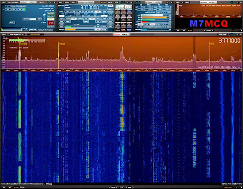
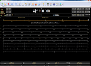
SO THAT’S HDSDR RUNNING! You can stop there and enjoy it. 


Many people will be satisfied with HDSDR but personally I think SDRPLAY's SDRUNO is infinitely more sophisticated and offers better control of the radio. And the good news is, once you've got HDSDR up and running, it's then simple to add SDRUNO because HDSDR installs everything that you need.

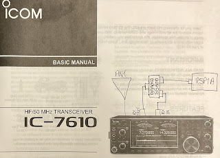
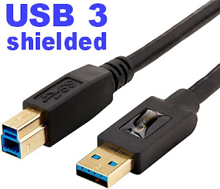
So the first step is to install HDSDR and get that running, following the very detailed and simple instructions in the IC-7610 manual. PLEASE NOTE that you will need a good quality BLUE USB 3.0 LEAD and a computer with a USB 3.0 socket! If you don't have both, don't bother trying to install any of this software. The IQ output from the IC-7610 comes from that BLUE USB 3.0 socket. 

DO NOT skimp on quality when buying this cable - buy a double-shielded one of good quality!!!  And don't buy one longer than you need to. Use a piece a piece of string between your radio and PC to determine the minimum length of cable you can get away with.

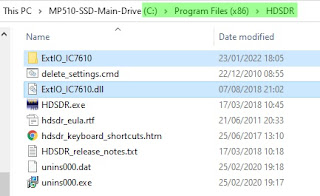
So with HDSDR installed and running, you now need to copy a folder and a file to the "DOCUMENTS FOLDER" of your PC. That folder and file can be seen in the image below. Locate them, copy them and then paste them into your Windows documents folder.


Now you're ready to download the SDRUNO SOFTWARE and install it as normal. If you are asked which SDRPLAY device you will be using with the software, just select RSP1A (it doesn't really matter which because you won't be using one anyway). You only need to download one file - SDR UNO! Don't bother with anything else.

People might wonder what makes SDRuno better than other similar style software and to me, it's not so much the functions and features (although that's very important), it's the efficiency of the software in terms of how slick it is, how fast it operates, how glitch-free it is and how regularly updated it is.

Install the SDRUNO SOFTWARE and you will end up with an SDR UNO icon on your desktop but that is NOT the one you'll be using to open the software. If you double-click that one by mistake, it will go looking for an RSP1A device, won't find one and will close down.

What we need to do to start the software is run a different tool. Go into your Windows Menu by clicking in the bottom left corner of your desktop and in the list of programs, find SDRPLAY and go to the SDR ExtIO icon and right click it so you can run it as Administrator (you can save a copy to your desktop while you're there). 

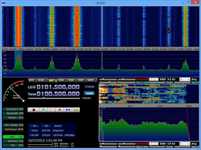
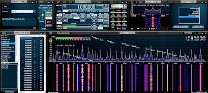
The software will now run and will start with the initial panel open. From there you can click on the buttons to open the RX window, SP1 & SP2 to open the scope and waterfall. If you're used to SDRuno, you'll very quickly figure it out, but if you're new to it, you'll probably have to watch a few YouTube videos to understand and fully benefit from this fabulous software.

If you try an older version of SDRuno that is already on your PC, you'll need to pay particular attention to the part of the instruction videos relating to separating the tune frequency from LO frequency! It's a minor point which if ignored will cause you much grief. I think the very latest software may have removed the requirement to offset - you'll have to check.


I should point out that my computer had OmniRig pre-installed and I don't think you need it for this application, but just in case you end up needing it - you can find the software HERE.

That's it! You've got some of the best software in the world running on your PC and controlling your IC-7610. Best of all, it's FREE! The only cost is about 20 minutes of your time. I'll explore more and report back on how practical and useful it is.

Please leave any comments below - and thank you for visiting the blog.

73, Tom, M7MCQ.


UPDATE  30 JAN 2022

After installing SDRuno, I'd been using it as an extra receiver but a friend of mine wanted to use it to control his 7610 completely, so I was on the phone with him trying to sort that out. To be honest, I didn't actually think there was a problem, but we learned that SDRuno wasn't keeping the Radio freq, Tuned freq and LO freq synchronised if you clicked on a signal in the scope.

Adjusting frequency with the mouse wheel was fine, but not if you clicked on a signal.

There has to be a way to resolve that issue and I'll update when I find it. I noticed also that opening the SDRuno software with the ExtIO icon meant that there was no SaveWS button to save your workspace, so each time you open the program, you have to lay out the various panels all over again. 

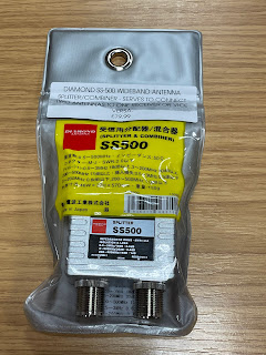
I might end up simply connecting my RSP1A to the RX-OUT of the IC-7610.

Update 3 FEB 2022

Apparently, SDRuno V1.4.1.1  has a bug which is causing this inability to click on the scope to tune when using IF output mode as opposed to using RF. It will be fixed soon.


Thursday, 20 January 2022

A SHORT TRIBUTE

UNCLE ROBERT

Bit of a strange post this one and although it's not about amateur radio, it also is about amateur radio. And that's because a lot of what I am today, is (in part) related to what my Uncle Robert did.

When I was a baby, my Dad died from stomach cancer. Back in the 1950's he and his brother left Portadown, Northern Ireland and set off for a new life in nearby England. Bolton to be specific. I've no idea why they chose Bolton, but knowing that their family of 13 were living in a tiny 2-up, 2-down, I can see why they wanted to leave their Irish home and seek new opportunities elsewhere.


I guess that after my father's death, my Uncle Robert felt it was his duty to step forward and donate some of his time to me and most weekends I would walk over to his house half a mile away. 

 
Everyone tells me that my father was a very friendly, outgoing, warm and sociable person, but I don't remember Uncle Robert being like that. To me, he was a little gruff and unsociable. He had a very strong Irish accent which made it very difficult for a young boy to understand and my Aunty Gertie used to shout at him and tell him to speak more slowly. He never wasted words - why use ten words when a hand gesture would do?

Despite his seemingly sharp character, he was in fact a very loving man and although he had no money to speak of, he always made sure that he'd got enough to put petrol in his old Ford Popular to take me for an exciting drive to Southport or Blackpool. He would save up pennies and halfpennies in a bag and then give it to me when I reached the fairground or pleasure beach.

 
It was all like being in heaven, because when I got back home, life was very different, filled with drunken violence and aggression thanks to my wife-beating step-father. If I could have lived with my Uncle Robert, I would have moved in a heartbeat.

More than a provider of rideouts and bags of pennies, my Uncle Robert was also like a teacher of all things exciting. He was a railway engineer and had a passion for anything to do with trains, planes and automobiles. He was keen on learning about mechanics, electronics, radio and TV. Even though he knew it was going way over my head (due to a lack of understanding and a lack of translation), he insisted on showing me how he was going to repair the distributor on his car and maybe adjust the valves. 

As a young boy I had a great interest in radios and reveled in listening to those distant stations fading in and out of earshot with their strange language and odd music. Back then you could listen to boxing matches on the radio! 😲

He collected model cars and model motorcycles and taught me how to build and paint them. Motorbikes were another passion of his and although he never took me for a ride, he would always involve me in the servicing and maintenance of it.

I remember he'd save me his magazines and when I was ready to go home he'd give me a carrier bag with various mags inside. Little did I know how all these things would impact and guide me later. 


Sadly, as I got older, I visited less and less. I discovered the value of girls and pretty soon I was married and having kids myself. Occasionally, I would pop over to see him, to maybe show off my new motorbike (which he thought was just one of those new-fangled rubbish Japanese things). He tried to get me interested in his model railway layout that he'd built in the spare room but I was having none of it and I rode off down the street in a plume of 2-stroke smoke.

And before I knew it, he was gone.

Shame on me!!  I always regret being that selfish teenager after he spent so much time providing safe and happy memories for me. He taught me to become curious and he planted countless seeds of interest that would grow into enjoyable hobbies for me later in life.

His influence had led to me serving my time as a car mechanic. I had a passion for cars and motorbikes. I became interested in electronics and used to love making little projects each month from Practical Wireless magazine. I became an avid ShortWave Listener and later an Amateur Radio enthusiast.

I owe a lot to Uncle Robert and although I was the typical selfish teenager, I do remember him and recognise my debt to him. He was a fabulous Uncle - the best! 💖

Saturday, 15 January 2022

QRP-LABS QDX REV.2 REVIEW

 BUILDING THE QDX 'REV2' BOARD

I recently built the Original QRP-LABS QDX (Rev-1) and everything went very well. It was an enjoyable kit and so I thought I'd purchase the Rev.2 board so I could keep one in the shack and stick one in my 'go-bag'.

I'll state right now that this build did not go well initially - there were problems which drove me nuts and I later found out that it was nothing to do with anything that I'd done - it was a fault on the PCB.

I chose to record all the details of the build (and the struggle) so that anyone else who experiences similar problems may benefit. Bear in mind that this is written from the perspective of a BEGINNER with virtually no electronics knowledge. So here we go....

Part built


29 DEC 2021 The QRP-LABS QDX Rev-2 didn't take long to arrive and I was happily putting it together over the Xmas holiday break. Although 
I know nothing about electronics, I do have a good mechanical aptitude and I'm perfectly capable of soldering components together, whether they like it or not 😂

This updated kit thankfully didn't have any SMD parts to worry about and I found it extremely easy to build. If I say so myself, I did a great job of all the toroids and was especially proud of my L12 with its awkward taps. It was much neater than the first one I did.

It fitted onto the PCB like it was made to measure and I experienced no problems. Neither did I have any problems with the trifilar T2. I took my time with it and made doubly sure that I had the correct A-A, B-B and C-C. I even went to the trouble of colour-coding them with a touch of acrylic paints (my other hobby is painting) 😊


After a few hours, the kit was finished and ready to plug in. Everything had gone together really well and I wasn't expecting to have any operational problems with it. I had followed the newly revised Assembly Manual (V1.08) to the letter and had carried out all the prescribed checks along the way.
_________________________________________________

WINDOWS 11
FIRMWARE 1.03
BUILT FOR 9V OPS


Before I loaded WSJT-X, I decided to run the PuTTY app and try some tests. The first test I chose was the Transmitter test. Using a SotaBeams Dummy Load and an MFJ-813 meter, I could see that it was putting out a solid 5W.The main LED was flashing 3 times during tx, as it should.

TIP : If you can't make out how many times the LED is flashing, record a video of it on your phone and play it back in slow motion.
 
I then chose to run the Audio Filter sweep. The results were not good at all 😢...


Next up was the RF FILTER sweep and I wasn't expecting anything good from it. I was right to feel that way because ever time I ran it, it swept up to 100% and then completely locked up. Ctrl-Q didn't work and I had to force the whole app to terminate. This app works perfectly with my Rev.1 QDX.


Feeling very dejected, I decided to do a Factory Reset but I knew it was a waste of time because I'd not actually altered anything in the first place that might cause an issue! Needless to say, it made no difference, so I decided to run WSJT-X. Well I wasn't really prepared for what I saw.....


Jeez!! What was going on????

I powered down and looked at the PCB again. Everything seemed perfect! I used a huge magnifier and a strong headlight to examine for stray solder traces, but there were none. I know this is not exactly a beginners-kit, but it's not rocket science to insert components into a PCB and solder them, is it??

I was puzzled and the ONLY thing that I could possibly have done wrong is the trifilar T2. Maybe after all that colour-coding I'd got it wrong??? No way! But it was the only component that had the potential to go wrong. So I got my multi-meter out again.

Doing the recommended A-A, B-B and C-C checks for continuity, showed no issues. Continuity was present in all three checks. BUT THEN I noticed that there was continuity between all the contact points 😱

I checked the manual to see if I'd missed any instructions to check for NO CONTINUITY between A-B-C. There wasn't any. So I was in a dilemma. Should there be continuity between all these points???

I had no choice now but to cut T2 off and desolder the bits left in the pcb. I then proceeded to carry out a continuity-check on the bare contact points on the pcb where T2 sits. I found that there were indeed some continuity between some of the contacts (see videos below). 

WHILE I HAD T2 ON THE BENCH, I tested it with the multi-meter to confirm that there was only continuity where there should be (A-A, B-B, C-C) and nowhere else. The test was all clear. So this gave me the comfort of knowing that I hadn't got it wrong.

Since there was nothing else I could do, I rewound T2 and after checking I'd matched up the correct pairs (over and over and over), I reinserted the toroid and tried it out using PuTTY and WSJT-X.

Same results 😡😭😡😭😡😭

I have no idea what's going on. I can only hope that Hans (or some of the other clever guys in the GROUPS.IO)  can offer some help. I'm totally cheesed off and puzzled.


Another test done (at the helpful suggestion of a GroupIO member) was to test R18 which came back as ZERO resistance. That was with T2 removed.


I'll update when there's something new to say. 😰

73, Tom, M7MCQ.


UPDATE 3 JAN 2022

Since Hans has not had time to respond with any suggestions or instructions to take measurements at specific points, the project has pretty much come to an end and I'll just have to forget about it for now and revisit it later - no point keep stressing over it when there's nothing further to be done at this time.

Thankfully, I have my original Rev1 QDX build to play with. That works superbly.

UPDATE 6 JAN 2022

I’ve had plenty of amazingly positive and helpful comments on GROUPS.IO trying to help me resolve the issues (along with the odd smartass remark), so I’ve decided to forge ahead with diagnostic and repair efforts. More later….

UPDATE 9 JAN 2022

At the suggestion of members of the GROUPS.IO,  I had measured the voltage on IC3 and IC4…

IC3 PIN9 = 2.5V
IC4 PIN7 = 0V
IC4 PIN9 = 0V

I was advised to remove C38 (which appeared to be shorted) and retest IC3 & IC4, so I did…

IC3 PIN9 = 2.5V
IC4 PIN7 = 2.5V
IC4 PIN9 = 2.5V

Since I don’t own an LC Meter, I couldn’t measure the value of the C38 cap, but it certainly displayed a short.

This thing has been a Major PITA and I have been so frustrated with it all compared to my Rev1 which is running superbly.

It turns out that the board I received from QRP-Labs had this dodgy cap right from the start, so I’ve ended up wasting lots of my precious leisure time. I can’t deny being a bit miffed about it all. I wish I could just start afresh with a new board!  I cannot even imagine soldering an SMD cap back in!

Anyway, I’ll just have to send a support ticket in and see what happens.

My next update will hopefully be my last one (and a positive one).

M7MCQ.


UPDATE 14th JAN 2022
The End Game!

After submitting a Support Ticket to Hans via the official website, I received a reply telling me that it would be extremely rare for a capacitor to fail, let alone as a short (even though I'd already said the cap WAS shorted out).  He said he could see four possible options....

1) Find someone (in UK) who can solder on a new C38 (SMD)

2) Return it to me in Turkey to solder on a new C38 (SMD)

3) We send you a whole new kit - NOT a preferred option!

4) Find any similar capacitor, or higher value, which is an ordinary through-hole component, and solder one end of it to the appropriate wire of the trifilar transformer, and the other end to a convenient nearby ground point.

Well I was already feeling a bit miffed about all this trouble with the kit, so I wasn't really in the mood for Option 1 or 2.  

Option 3 might result in a wait of weeks or months for the next batch of pcb's so that wasn't an option either.

So Option 4 seemed like my only real option. So I ordered some through-hole caps and waited for them to arrive. It only cost me a couple of pounds but as usual, it's the waiting that cheeses you off, so I paid for express-delivery which cost me much more than the caps.

So when the caps arrived, I went to install one as advised by Hans. He said it should be fitted between the two top trifilar connections (images below). I found it quite tricky to do until I temporarily applied a blob of Blu-Tak to hold the cap in the right place until I'd soldered one leg successfully.


Once the cap was soldered, I checked the AA,BB,CC connections and all was well, so I laid down a small piece of tape to prevent the cap legs touching anything they shouldn't - just a precaution.

Now it was time to fit the pcb into its case and connect to a PC!

I first of all connected it to the PuTTY App and ran all the usual tests. Everything was looking pretty good apart from the 80M RF SWEEP  which looks odd and I don't know how to resolve it. I reflowed L12 contact points and even tried adjusting the spacing of the coils around the 80M section but nothing has made a difference and the receive is excellent anyway.


Next up was the AUDIO FILTER SWEEP which looked acceptable to my eyes...


POWER TESTS revealed a full 5W on 80, 40, and 30M but only 3W on 20M 😮

On WSJT-X  the receiver was pulling in signals NO PROBLEM!! All bands pulled in lots of signal reports, so it was now time to ENABLE TX and see if I could make a contact with someone.

To my sadness, I couldn't manage a single QSO. I tried many times but not a single operator responded to my calls. I tried pouncing on the end of other contacts and then just called CQ for AGES! No contacts.

With that poor result, I looked at PSK REPORTER to see if my 5W were actually reaching anywhere and I was pleased to see that I had got as far as TURKEY ( over 3,200Km @ -19dB) from my QTH here in England . So I was getting out!


I was puzzled!!  I switched over to my Tried & Tested QDX REV-1 and tried again using the same antenna, band, mode. I'm pleased to say that that too failed to make any contacts, so it was not necessarily the fault of the new build.

I will try again when conditions are better and see what happens.


73, Tom, M7MCQ


UPDATE 15th JAN 2022
FINALLY!

So, new day, new start. Plugged the QDX in and set it going on WSJT-X FT8 Mode. It wasn't long before I was making contacts. Not loads - but it confirmed that everything is working normally. You have to remember that this is a QRP transceiver and you have to work quite hard to get a contact from CQ to RR73.


In between contacts I put together a DC-DC Voltage Step-Down unit that I'd bought on eBay. It was only £6 so I thought I'd take a chance on it. It allows me (with adjustment) to drop my Shack PSU's 13.8V to 9V. I was concerned that it might be noisy but everything seems fine and the contacts are coming in and the waterfall is showing no noise artifacts, so all good so far!

I put the little pcb into a hobby box that I'd got laying around and secured it in place with my beloved Hot Glue Gun, LOL. The specs (if you're interested) are....

Input voltage: 4-38V
Output voltage: 1.25-36V continuously adjustable
Output current:0-5A
Over 3A, attached the heat sink.(recommended for use within 4.5A for long time use)
Output power: recommended for use in below 75W
Working temperature:-40 to +85 degrees
Operating Frequency: 180KHz
Conversion efficiency: up to 96%
Load regulation: S (I)<0.8%
Voltage Regulation: S (u)< 0.8%
Short-circuit protection: Yes (the limited current is 8A)
Over-temperature protection: Yes (automatic shutdown when over-temperature)


16 JAN - UK to JAPAN on 4W 😃


So, here we are at the end of what was a problematic build. At one point I was just going to abandon the kit because I value my time too much to waste it on things I can't seem to repair. It was only because of the encouragement of some of the members of GROUPS.IO that I persevered.

Lots of people tried to help me and most members were extremely kind and encouraging - THANK YOU!!!

I should give special mention though, to one particular individual who not only helped me, but who also helps everyone!! He must spend an enormous amount of his spare time helping people out. That person is Evan Hand (AC9TU). He helps and guides people without a hint of sarcasm or smartass remarks. THANKS EVAN!!!


If you have any comments or questions, please leave a message below. And thank you for visiting my Blog.

73, Tom, M7MCQ.