Monday, 26 August 2024

QRP-LABS QMX *PLUS* PART-2

The first build of the QMX+  (HERE)  ended up being a fail due to a short inside the CPU. Needless to say I didn’t make this diagnosis - it was a guy called Ian (G4GIR) who very kindly offered to examine the kit for me and he in turn received technical guidance from Jeff (W1NC) - I thank them both for their extremely helpful assistance.

As a result of Ian and Jeff’s help, I was able to convince Hans that the fault was not of my own making and so he sent over a replacement PCB and other components (but not the toroids). This meant that I had to reuse the old toroids, but rather than trying to desolder them all and then struggle to get them to fit with extremely short ‘legs’ (which would be nigh on impossible - it was tough enough originally), I decided to rewind them. Thankfully, I had two bobbins of the correct thickness enamelled wire.

The first problem though, was removing the hot-glue that I’d applied to the toroids on the original pcb! 🙄


Before I installed a single component onto the new pcb, I hooked it up to a PC with a USB-C lead and fed the pcb's Vdd with 3.3V (current-limited at 200mA) to make sure that the board showed up as an external drive - it did! 

I wish I'd done this on my original kit because it would have showed that there was something wrong with the pcb because I wouldn't have wasted all that time and experienced all that frustration. It should be the first instruction in the build-manual.

Once I started the new build, it went together pretty quickly, although I will say again, it was a bitch to solder! I’ve never come across a pcb that’s given me as much trouble. It seems like the ground plane is huge and the solder pads are tiny.


Throughout the build I checked for a short between Vdd and Gnd. There were no issues this time and before I knew it, I was ready for the first power-up (again with a current-limited power supply set at 7V/200mA). The QMX showed up as a flash drive again on my PC so I dragged the firmware across to it and rebooted the radio. Bingo!….

With everything seeming to be working fine, I raised the voltage to 12V and tuned around for signals. I’m pleased to say that it seemed to be working okay, so then I tried some transmissions through my EFHW and searched the RBN to see how far I’d reached.


Once I could see that I was getting out well, I put the case together and tuned around the bands to test the CW Decoder - it was working really well!

So for now, I’m very happy! I’ve not done any proper testing of each band because I’ve had enough for now 😂 😂 I’ll do more tests next weekend and update this page.


When you make a warranty claim against a small company like this, you feel kinda bad about it and some people try to make you feel even worse, but when the claim is totally valid, I feel no guilt whatsoever and expect a very positive reaction from the supplier.

In the case of this build, the claim was appropriate and it was handled superbly by Hans Summers, without any delay or hesitation and I absolutely appreciate that. So much so that I went onto his donation page and made a voluntary contribution as a thank-you for making it easy.


UPDATE - TEST RESULTS<<<

Okay, so after successfully building my QMX+ 😵 I connected it to a PC and ran the terminal-emulator PUTTY to run some tests. I haven't evaluated the outcome - for now it's just a case of running the tests and grabbing screenshots. They may be of use to other kit-builders.

AUDIO TESTS


DIAGNOSTICS TESTS


RF TESTS


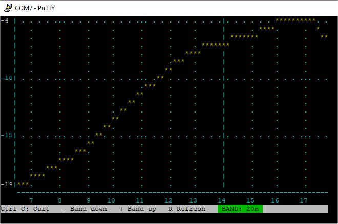
ADC I/Q TEST (all bands similar)


The main area for concern is in the AUDIO TESTS where the separation between the two traces is not particularly good - especially on 20, 30 and 40M. Well, that's how I'm reading it anyway! Your comments are very welcome and so too are your recommendations for how to improve the readings.

The DIAGNOSTICS readouts don't ring any alarm bells with me and I'm quite pleased with the power-output on most bands. As for the rest of the figures, I'm not really sure what I'm looking for. Again, any helpful comments would be greatly appreciated.

The RF TESTS indicate (to me) that 20, 40 and 80M need some work. How to improve those readings - I have no idea.

I'm guessing that the first approach should maybe be to REFLOW all the solder joints on the toroids, followed by a redistribution of the windings and see what changes. Other than that, I'm at the mercy of you, the readers 😊🙏


UPDATE <<<<<

28 AUG 2024

For the tests above, I had used a cheap Dummy Load that I'd bought from a rally, and tonight I decided to try the tests again with a good quality Dummy Load. There was quite a big difference in the readings!  So before you run your tests, make sure you are using a good DL with sound connections.

Having seen the new readouts, I feel quite happy with the results 😍


The only thing remaining to do with this kit is to install the GPS unit, which I’ll do shortly.

  UPDATE!  

I carried out a mod to add an internal speaker - see HERE!


  UPDATE!  

SSB FIRMWARE!! Today I installed the latest firmware which adds SSB MODE to this amazing little radio. What a fantastic machine this is! 💖💖💖


PLEASE LEAVE A COMMENT BELOW!

(Either anonymously or with your callsign)

Thanks!

73, Tom, M7MCQ.


 .

.


QRP-LABS QMX *PLUS* PART-1

Last Easter I built a 5-band QMX and although I found it quite a challenge, it worked from the get-go and I was really pleased with myself! I get a lot of pleasure from building electronic kits and this will be the sixth one from QRP-Labs


My only gripe about the QMX build was that the design left the components incredibly tightly crammed in, and I wondered why they hadn't made the PCB just 10mm wider. But since then, I have read Hans Summers' document explaining that, for him, it was a design-challenge to come up with such a compact design. Well, he did an amazing job!!

Anyway, here we are a year later and I see that Hans has released the QMX+ transceiver kit. This time, the design has much more space between components and I'm anticipating that the build will be far easier than the original design.

So what is a QMX+?? Well it's a high quality 12-band MultiMode (CW/DIGI) Transceiver which can be purchased as a self-build kit or as a pre-assembled unit - it's worth noting however that there is a very long waiting list for pre-assembled units - maybe up to 6 months 😮

In terms of functionality, the "PLUS" version is little different to the standard QMX but it has the advantages of being able to house a GPS unit, an SWR Bridge, a Real Time Clock (battery backed), a Developer's Kit and maybe even an ATU in the future. Hans also has other "secret" plans for the ongoing development of the QMX+ including SSB Mode which will be awesome!

I feel (and I may be completely wrong) that the QMX+ is a big step toward the release of the fabled QSX which will be an All Mode transceiver with who knows what features. 

I currently own a couple of (tr)uSDX transceivers and these are simply amazing little radios which are multi-band, all-mode SDRs with built-in speaker, mic, keyer, PTT, CW Decoder etc. But their performance is far from perfect. Don't get me wrong - I love them - and when you're up on a hillside playing POTA or SOTA, their performance will bag you many contacts for little outlay. But they're just not in the same league as a QRP-Labs product.

I'll always remember when I built my first QRP-Labs kit - the QDX. It went together well and it performed superbly!! I was getting better results on my 5W QDX than my Multi-Watt IC-7300.  I was (and continue to be) very impressed!

Sorry - I'm rambling. Let's look at the QMX+ Kit. It arrived in a single box which contained all the relevant components, each type being bagged separately.  I'd also ordered the optional GPS Module plus (of course) the metal enclosure. 

The quality of this kit is extremely high and I've yet to come across a QRP-Labs kit with missing pieces. The aluminium case is strong and well finished, with sharp text on the end plates.

The Assembly Manual for the QMX+ is extremely good (as usual) and I intend to follow the instructions to the letter, just as I've done before. 

In addition to having access to the manual electronically, I also decided to print a copy so that I could read through it prior to starting the build and highlight bits which I think warrant special attention, making notes in the margins of the page. I also use the printed manual to mark off each completed section.

I had decided to do this build at the weekend while I was at our caravan - nice and peaceful with no distractions. Prior to going there though, I wound all the toroids and then bagged them individually in tiny sealer-bags with ID labels.

All pretty straightforward but
the most tedious was L506

Before starting the build, I laid out all the components and marked off the capacitor values. Once that was done, I fitted the caps, the diodes and the inductors. Very simple.

After that I installed the BS-170 transistors, clamping them in place before soldering. 


Next up was to install all the toroids and the trifilar. Since I'd pre-wound these, it was a breeze to fit them all and once I've adjusted them as part of the 'tuning' procedure at the end, I'll probably drop a few blobs of hot-glue on them to keep them secure when the radio's in transit.


At this point of the build I realised that I was rocketing ahead and was being a little blasé, so I purposely slowed down and checked everything I'd done so far. 

You will soon notice that some of the solder-pads are TINY and it can be real difficult to get the tip of your soldering iron onto both the pad and the component at the same time. If you look at the adjacent image, you will see that some solder-pads are way, way smaller than others and some of the pads are barely visible. This is a multi-layer board and the ground really sucks the heat from your soldering iron, so make sure you use a decent one that can cope with it.

When it comes to winding the T501 Transformer, you have to decide whether you want a 9V radio or a 12V. I opted for 12 and for this you are strongly advised to choose the "RWTST" method of winding (Really Weird Twisted Sister Transformer) and boy, it certainly is weird!

I'll be honest and admit that the first time I wound T501, I wasn't confident I got it right, so I unravelled it and started again. I was struggling to understand the diagram (see below).

Diagram From The Manual

In the hope that it will help others, I have redrawn this and although it makes sense to me, it may not to you 😂....


After that, I put the two power boards together and fitted them to the main pcb. You have to be very careful to read the instructions and slow down when you're fitting these. Read a couple of pages ahead before beginning!! I totally forgot that the black connectors have to be mounted so that there’s a gap below them. I just about managed to get away with it (der!).

 
I then started fitting all the 'hardware' such as the BNC connector, power connector and 3.5mm sockets before installing the LCD panel and battery board.

With everything installed (don't forget the link under the GPS Board (if you bought one)), it was time to slide the PCB into the lower half of the enclosure. 


Before you do though, spend some time examining the pcb to see if any of the component legs need trimming down, because there's very little space between the underside of the pcb and the metal enclosure and it's very easy to end up with a short. 

I purchased some amazing little side-cutters from the local £shop which were perfect for the job! To be honest, I thought they might be junk, but they turned out to be the toughest fine cutters I've ever bought, so I went back and got another pair 😊

With everything put together it was time to apply power and see if any smoke emanated from the case 😬. In case I'd made a mistake (or two), I opted to use a current-limited psu to avoid damage on power-up.


 FIRST TEST >>>

When I switched it on, there were no lights, no display, no noise, nothing. And thankfully there was no smoke!

Before anything will work, you have to connect the radio to a computer with a USB lead and install the firmware, but when I did this, the USB was not recognised. I tried a different lead and even a different computer - nothing! 😰 

I checked and double-checked the pcb for any obvious signs of faults such as dry joints, solder shorts, etc, but there was nothing obvious. I could see 9V at the power switch.

I sought help on the Groups.IO forum and got nowhere initially, so I submitted a trouble-ticket at QRP-Labs but six days later there was no response from that either.

It's extremely disappointing when stuff like this happens and I know there's bigger problems in the world, but neverthless I'm feeling quite disappointed considering that I've successfully built 5 other kits from Hans (including the regular QMX which is much tougher build) and a few from other kit manufacturers.

A few days on and members of Groups.IO started to make suggestions and I learned that there should be voltage at Vcc and Vdd but there was none on mine. The thread got busier and someone suggested that I try swapping out the Power Boards from my QMX to my QMX+.  To reduce the risk of damaging anything, I was using a variable voltage/current PSU.  With it, I could reduce voltage to maybe 7.5V and 200mA.


Before swapping out the boards, I recalled my soldering struggles and decided to reflow virtually all the connections to make sure that I'd not got a bad joint somewhere which was causing these issues. The Ground Plane on this pcb really does suck the life out of your soldering iron! 

I decided to remove the power boards and the GPS module. It was then that I discovered I actually had a short on Vdd. No amount of probing with my DMM helped discover the source of the short, so I’ve given up for now.

I’ve approached an electronics professional friend to see if he can afford the time to do some fault-finding for me. If not, I might have to order another and start all over again 😪.

Part-2 to follow!


UPDATE >>>

Regrettably, my friend is in the process of moving to another country(!) so I'm now proper stuffed 😂 I guess I'm going to have to write this off completely. 

I was thinking of ordering another one and trying again, but this build has made me a little weary. Plus it's highlighted the fact that without any electronics knowledge, I've just been a lucky constructor up to now.

I'll have to sleep on it 😓

UPDATE >>>

On a more positive note, G4GIR very kindly offered to look at the board for me, so I've popped it in the post to him and await his verdict. Let's hope it's nothing I've done 😂😂😂


UPDATE >>> 4 July


Ian G4GIR has carefully examined the pcb and has determined (with the very kind help of Jeff Moore W1NC) that the fault is with the main CPU, so that's nothing to do with me or anything that I've done wrong. In fact, Ian complimented me on my construction work.

I have since found out that others have had a faulty CPU including G0MGX, so maybe it's not that uncommon?

So I have written to Hans and I await his response - a positive one hopefully.

UPDATE >>> 11 July
Hans has very kindly shipped out replacement pcb and components to allow me to start from scratch. I will be looking for ways to carry out checks stage by stage from the forums this time.

73, Tom, M7MCQ.


UPDATE >>> 26 AUG

PART TWO of the build is >>> HERE <<<

This next post shows how I completed the kit and shows the final outcome 😊


Tuesday, 30 July 2024

FORBIDDEN FRUIT

There's so much hatred for FT8 and associated digital modes on social media that it becomes utterly boring!! I don't do a great deal digital work, but I'm sick to death of seeing people belittle other people's preferred mode of operation.

By far the biggest victim of this vitriol is FT8 and it pains me to see people tearing apart the enjoyment of fellow hams, claiming that FT8 will be the death of Amateur Radio, when the truth is, it has generated HUGE levels of interest and activity on all the bands, all the time and occupies a tiny amount of bandwidth and never encroaches on others.

Anyway, enough of all that - I am only posting this because I saw a little poem on social media that someone called Gregory Weisheipl posted and I kinda liked it...


FORBIDDEN FRUIT

In the quiet of the night, beneath the starlit sky,

A room is softly glowing where the radio waves fly.

Amateur radio’s magic in the dance of FT-8, 

Where signals cross the oceans in a digital state. 

No voices in the air, just pulses swift and bright,

As callsigns on the screen bring messages to light.

From distant lands they come, in bursts of code they greet,

In silent conversations, where strangers often meet.

With patience and with skill, they tune the frequency,

Each QSO a bridge, in this vast community.

From mountaintops to valleys, through the atmosphere they soar,

Connecting friends and strangers on a worldwide tour.

FT-8, a wondrous mode, with messages so brief,

Bringing joy and knowledge, in its quiet, coded speech.

Though words are few and fleeting, the bond is ever strong,

In every signal sent, we hear the same old song.

So here’s to every operator, with ears and hearts so keen,

Who find the joy in contact, in signals clear and clean.

Amateur radio’s charm, in FT-8’s embrace, 

A timeless way of reaching out, across the human race.


PS : The poem was generated by ChatGPT! 😮