Sunday, 10 March 2024

RADIO-KITS EXPLORER (PART-2)

 PART 2 - TESTING! 

Having previously posted about building the Radio-Kits Explorer, now is the time to switch it on and see if the magic smoke is released.

I had followed the instructions and run all the tests listed in the instruction guide. Thankfully, everything seemed fine and to spec, so I finished off the last bits of construction and got it ready for full operation. For the first switch-on I used a 12V 600mA psu and plugged it in. The radio lit up and made radio-like noises. No smoke!! ๐Ÿ‘

I connected an EFHW and checked the receive capability of the Explorer and I'm happy to report that everything is working really well! Thankfully, there was a contest running , so there were lots of SSB signals to listen to from all over the world. The narrow CW filter worked well too down at the bottom of the band. So far, so good! ๐Ÿ‘๐Ÿ‘๐Ÿ‘

Then I plugged the Explorer into a computer and Windows saw the device and assigned it a COM port ๐Ÿ‘

The PA BIAS adjustment was odd. It is set by default to 100, which is too low. When you select the option, the radio goes into TX (no RF) and the red LED lights up. The current draw went from 154mA (RX) to 285mA and adjusting the BIAS made no difference - it's supposed to increase the current draw and you keep rotating the dial until you've added about 40mA to the initial reading you got. 

Odder still, every time I return to the BIAS menu option, the figure has defaulted back to 100. I assumed it would maintain the adjusted level, but it doesn't. Apparently, this is normal but I’d personally prefer it to remember the figure. The reason Steve forces it to default to 100 is in case an owner changes the PA transistor. If I had to change the transistor, I’d probably do a full reset anyway.

The end result is that the radio isn’t transmitting. I tested it in CW mode on a straight key and every time I keyed-up, I saw a current draw around 280-290mA and the Power Out reading on the radio's screen was 0W. ๐Ÿ˜จ 

I wrote to Radio-Kits and Steve said he'd put together a list of things to check. 

 5TH MARCH 

Steve emailed back promptly and gave me some things to check...


With a 13.8V input and the receiver set to measure bias current (SYS MENU - TX BIAS - 100 - red led on), Point-1 should be around 13.8V and Point-2 should be 0V. They were both fine๐Ÿ‘

Next up was a resistance measurement between Point-1 and Ground (with the power supply disconnected). It should be 890 Ohms - it was ๐Ÿ‘

Next was the bias voltage. This involved setting the bias figure to 300 and measuring the voltage at Point-3. It should be 2.1V and it was. Voltage at Point-4 should be 1.5V and it was. ๐Ÿ‘

Next, Steve wanted to know the voltage at Point-5 (the PA transistor Gate) with the bias setting at 300. It should be 2V and it was. ๐Ÿ‘

He also wanted to know the current being drawn by the radio if the bias setting was increased to 400. The current didn't alter at all with the increase from 300 to 400. In fact, the current stayed the same even if I increased the bias setting to 1000 ๐Ÿ˜ฎ

If you're an outright beginner and you're not exactly sure how to use your multi-meter to measure current, see the diagram above. Be sure (in this instance) to pick the mA port on the meter. 

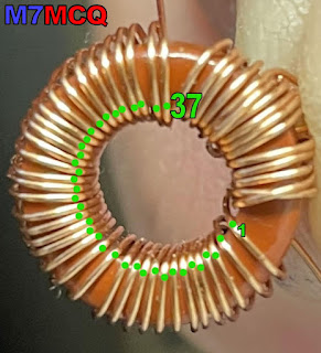
By this time, it was getting late into the evening, so we called it a day. Steve signed off with a note about the PA transistor, saying to check the voltage reading on the metal tab which backs onto the case and he also mentioned the connections on the T2 windings. I'll leave it for tomorrow.


 6TH MARCH 

I checked the voltage on the transistor’s metal tab and it read 13.8V which was correct. At this point, I took note of Steve’s suspicion that the output transformer (T2) wires might not be making contact.

Checking the wires with a continuity tester, everything seemed fine, but I decided to reflow the solder joints anyway and boom - it worked! Thanks for your guidance Steve!!

FULL 5W OUTPUT
With the radio showing a solid 5W into a dummy load, I rebuilt the radio and started to run some on-air CW tests. I connected an EFHW and used my Elecraft T1 tuner to get a good match. During the tuning process, I saw the output power vary between 1.5W and 6W. This prompted me to ask Steve if the Explorer had any built-in SWR protection and the answer was no.

He followed it up with a reassurance that it won’t fail as long as it doesn’t get too hot. The Elecraft T1 usually finds a match very quickly, so I’m not too worried about that, but obviously, you need to be cautious when using data modes such as FT8.

Once I’d got the radio matched to the antenna, I started to put out some CW TEST messages and within a minute or two of sending, spots appeared on the Reverse Beacon Network as far away as 1,100 miles away into Eastern Europe. Conditions were very poor tonight, so I was quite happy to see those. 

Later, I tried again and managed to make 3 contacts in the USA, over 3,500 miles away! I’ll try again at the weekend from a better location.  I also need to find a suitable microphone to run some SSB. 


While I've been fiddling around with the Explorer (especially during the testing phase) I thought that the radio would benefit from a Power Switch - so I fitted one!

I'd noticed that the PCB had two contacts marked power-switch and I asked Steve how these could be used. He explained that one simply needed to cut the track in-between the contacts and then route a switch to it. The problem, he said, was which switch to use and where to put it.

Well I looked around and bought some single-pole, single-throw, latching, push-button switches on Amazon and when they arrived, I discovered that they were much too long and would touch the PCB, so I simply fitted one of the fixing nuts above the fascia plate and one below. I then splayed the legs out and hey-presto, it fitted perfectly! If I can find a lower profile switch later, I'll swap it out.

I opted for a white colour to match the writing on the radio fascia. I think it adds a real convenience to the radio and saves you from repeatedly plugging/unplugging the power plug.

Modified with Power-Switch

I also made some other tiny mods which obviously make no difference to performance - it's purely cosmetic - but it personalises the kit you've just toiled over. Apart from the heatsink and the power switch, I also swapped out the case screws for some stainless-steel low profile cap-heads from ACCU. And finally, I fitted a black aluminium knurled finish tuning knob.

Oh, just for convenience, I also fitted a kick-back stand to angle the radio up toward me. These are actually sold as Laptop Stands and I've used them lots of times on portable radios. 


I do plan to make one more mod and that relates to the Mic Bias option. Inside the case there's a link which you fit a small jumper to if you want to introduce a 5V bias to the microphone for electret mics. I think I'll fit a small slider switch to the side of the radio to bypass the need to open and shut the case if you want to switch mics.

At the time of writing, the manual didn't include any diagrams showing the connector configurations, so I've knocked together a sketch below...

More testing... 

Obviously, I'm a Foundation License holder with no fancy test-equipment and even less expertise. All I can do is look at the Explorer from a practical end-user point of view and maybe compare it to a couple of other similarly priced radios.

To give a radio the best chance of working to it's maximum ability, I always test radios from a quiet location, where the noise floor is low and the take-off is good. I have a holiday home on the edge of the Forest of Bowland, so no better place to play radio! 

I decided to head up to a slightly elevated location called Bodie Hill above the Port of Lancaster. This place overlooks Morecambe Bay, out toward the Irish Sea and beyond. It's a great take-off point and it's also a beautiful place to work from. It's weird how you can see ships floating above the houses at Sunderland Point. One of my favourite places to operate from, not least of all because there's loos and cafe's not too far away ๐Ÿ˜‚


Because I'm working a single band, I setup with a 20/40 Linked Dipole from SotaBeams - it can always be relied upon for great results as long as you've got the space to erect it. If I didn't have the space required, I'd use my Super Antenna MP1 Vertical on a tripod.


The first thing that I normally notice when I switch on a radio here, is the stony silence, but the Explorer has around S3 noise with no antenna connected. When I was at home, I'd blamed the local QRM, but no, it was the same here too. Now bear in mind that it may be due to my build-skills and not the radio. Or it might just be the way the S-Meter is setup ๐Ÿคท‍♂️.

As I tuned around, the incoming signals negated the need for a super low noise floor anyway - almost everyone was S5 to S9+ anyway and boy, did the signals flow in - it was a busy day on 20M.

I tuned to the CW portion of the band and put out some CQ TEST messages to see how far my signal was being spotted on RBN. I spent a few minutes doing this, changing the frequency each time. I'll download the report later.

To use SSB I plugged in a TNT microphone that I'd hurriedly made up to suit the jack-plug configuration of the Explorer - I was using a non-electret mic on this occasion. I found someone calling CQ and went back to him, unsure if the mic was actually working. He came back to me immediately, confirming that I'd got the wiring right, lol.

He gave me a 59 from Bykovo, Russia, which I think was more of a bouquet of flowers than a true report, but I took it anyway. He certainly wasn't struggling to hear me.

Next up was a contact in Lithuania, followed by two Germans, an Italian and an American guy in Austin, Texas! I got great signal reports from everyone, apart from the Texan, who gave me a 4/0. Despite this, I was talking with him longer than any of the others, so he had no problem copying me. He was very impressed with the fact that I was using a kit-radio and asked for the manufacturer's website.

After a few more SSB contacts, the rain started to pour and made a cold day, colder! I was happy that I’d tested the radio sufficiently enough to draw conclusions on its performance, so I packed up and headed back to the caravan.

Back home, I was interested in trying out different mics and I tried to alter the mic-gain, but Steve informed me that it's not variable - it's fixed by R29 at 100k. So I will have to spend time playing around with other mics which means cutting connectors off and fitting new ones ๐Ÿ˜จ 


CONCLUSION 

Let me preface this by saying that I really enjoyed building this kit and I am really pleased with the finished product, including the form factor and that blue case. It is not a compact radio like a (tr)uSDX or a QMX and doesn’t try to be. In fact, its size makes it A) unique in the marketplace and B) easier to build. In contrast, QRP-Labs seem to have gone to great lengths to keep the QMX as small as their QDX by using a 6-layer pcb and construction methods which can make the build quite a challenge (although their instructions are second to none).

The Explorer construction/user guide is perfectly adequate for seasoned kit builders, but I’d say it’s a bit lacking from a novice’s point of view. Having said that, the designer acknowledged this and is about to make some alterations.

The radio does not have a bootloader, so there’ll be no firmware upgrades available through the USB port - something we’ve all become familiar with in recent years, to the point that we now expect it.

Ergonomically, I’d say the radio is lacking. There’s only one controller and that makes some tasks a bit laborious. I was quite shocked to find that you cannot change the Tuning Step unless you use CAT Control ๐Ÿ˜ฎ, although the Explorer does feature Progressive Tuning, where the tuning rate increases the faster you spin the dial. I’m not sure how much would be involved in a redesign  to include a second encoder or additional function buttons, but I’m sure it would make a huge difference to the enjoyment of the radio.

Performance-wise I found the receiver to be quite sensitive and selective when fed with a good antenna in good conditions. It was definitely better than the (tr)uSDX but not massively so. 

In terms of value for money, I guess the Explorer doesn't do well compared to the competition. For less money, you can buy kits which provide you with five times as many bands to play with, more modes, lower power consumption, better ergonomics, a built-in microphone, ptt/morse key, morse decoder, memories, swr bridge, colour screen, firmware upgrades and more!

It sounds like I’m not very happy with my purchase, but the fact is, I’m glad I bought the Explorer and for me, it’s a keeper. As I said previously, I love building these kits and Radio-Kits.co.uk have made something that is just that bit different.  If they bring out a V2 with a richer feature list and better ergonomics, I’d buy that too!

But I’m not normal ๐Ÿ˜‚ Most people buying a kit-radio would be doing so to save money and they’d be keen to get the best feature-set for the least money. This is where the (tr)uSDX really makes sense. So too does the QMX, even though it currently doesn’t include SSB (although future firmware upgrades will add it). If your main modus-operandi is CW, then the QMX would easily win out here, thanks to its click-reducing envelope shaping.

Anyway, I’ll be keeping my eye on the Radio-Kits website and look forward to any new additions to their range.

If you have any comments, please leave a note below and try to include your callsign.


73, Tom, M7MCQ.


UPDATE 14 MARCH 2024

I have been testing microphones and experienced a rather big issue. For some strange reason, my transmissions sounded DREADFUL!!! I had the power output on the Explorer extremely low and was listening in on my RGO ONE. Every time I keyed up and spoke, the audio was shockingly bad.

I couldn't understand what was going on, because I was calling CQ all last weekend and had been getting great reports!

I approached Steve and explained what was happening - he was baffled like me. He asked if there was power out when I spoke into the mic and I told him, yes. He said he'd give it some thought and get back to me.

I returned to the radio and transmitted some more, but this time I turned the VFO dial on the RGO ONE - boom - it was then that I discovered the Explorer's VFO Calibration was out by 70Hz ๐Ÿ˜ถ

Lesson learned - RTFM! Well in all fairness, I didn't really think I'd need to calibrate the VFO after reading this part of the manual...

VFO Calibration Frequency calibration will already be close due to use of a TCXO but may be improved if required.

I should, of course, have checked though. All my fault.

73, Tom, M7MCQ


Wednesday, 21 February 2024

OFCOM'S LICENSE VARIATION

OFCOM'S LICENSE VARIATION IS NOW ACTIVE!

As of today, the 21st Feb 2024, OFCOM have announced that the new variation to license has come into effect. Full details are below (click to read the PDF file)...


Wednesday, 14 February 2024

STREAMDECK & FLEX 6300

EXTERNAL CONTROL FOR FLEXRADIO 6300

Because I have a 32-Button StreamDeck and a Flex-6300, I thought it would be a worthwhile little project to link them both together. Needless to say, it wasn't as easy as I thought because the SmartSDR software doesn't have native keyboard mapping, so you can't apply keystrokes to buttons as you might normally do.

It seems that the way you go about this sort of thing is to use a very popular 3rd-Party piece of software called FRstack which virtually every Flex owner will be aware of. FRstack (V3) allows you to assign tasks/events (even multiples with tailored delays in-between) to StreamDeck Buttons.

I should point out straight away though that if you assign certain keyboard characters to a button (such as SpaceBar=PTT), you will end up keying your mic everytime you press the spacebar whether you want to or not (as long as FRstack is running). So it's better to avoid doing that, except maybe the F1-F12 Function keys.


Of course this meant a lot of learning and no doubt a string of cock-ups before making any progress, but thankfully, Erik Carling (EI4KF) had already used his blood, sweat and tears getting the StreamDeck to function properly with FRstack - and therefore with SmartSDR. Without Erik's mighty contribution, I'd still be wrestling with the commands. Thank you Erik for sharing your profile ๐Ÿ™

Some of Erik's profile worked and some of it didn't. The errors were no doubt due to differences in either our ownership of software or their file paths - who knows? So as it stood, I couldn't make use of Erik's profile BUT it was incredibly helpful in letting me understand the command syntax. The video below by David Deccons was also helpful...


After an hour or so I managed to start a new profile and create an initial layout of my own. Needless to say, it's not perfect and I plan to spend a lot more time refining it, but at least I feel like I've made some good progress tonight.

One good little tip I learned was that it's easy to see a button in someone else's profile (eg EI4KF's), copy it and then switch profiles from the drop-down and go to your own profile and paste the button. It will bring across the icon, the text and the actions. You can then tailor them accordingly. Saves you a bunch of time!

At the weekend I'll try new things and I'll reorganise the button layout after spending time using the SteamDeck with the radio. I already feel like I don't need half of the screens. I might end up creating a separate simple single or double screen profile with JUST the very common button presses that I find myself doing all the time. 

Back soon!


UPDATE

After all that messing around, I soon realised that multiple presses of the StreamDeck screen took up more time than just moving the mouse and clicking!

So I chose the functions that I change most frequently and put them on the front screen. There's a second screen with other software which gets me launching apps quickly.


KISS huh?  I can see this front panel changing pretty frequently as I start to use it and discover what I like and don't like.

73, Tom, M7MCQ.


UPDATE : 
Here's a list of commands that might be of use to anyone wishing to create more complex profiles than me.

Radio cmdval Parameter
INFOreturns radio information
ENUMINFOreturns radio properties enumeration information
ACC0 turn off, 1 turn on, other toggle setting
AMCARRIERUP* to increase level, DOWN* to decrease level, or carrier level
AMPOPERATE0 turn off, 1 turn on, other toggle setting
ATUParam values are START, BYPASS or CLEAR
ATUMEM0 turn off, 1 turn on, other toggle setting
AUDIOGAINUP* to increase level, DOWN* to decrease level, or audio level
BINAURAL0 turn off, 1 turn on, other toggle setting
CLIENTNEXT to switch clients, or set client station name, returns client station name
CLIENTSreturns list of clients
CWBREAKIN0 turn off, 1 turn on, other toggle setting
CWDELAYUP* to increase offset, DOWN* to decrease offset
CWIAMBICMODEA0 turn off, 1 turn on, other toggle setting
CWIAMBICMODEB0 turn off, 1 turn on, other toggle setting
CWPITCHUP* to increase offset, DOWN* to decrease offset
CWSIDETONE0 turn off, 1 turn on, other toggle setting
CWSPEEDUP* to increase offset, DOWN* to decrease offset
CWSWAPPADDLES0 turn off, 1 turn on, other toggle setting
CWX1 - 12 transmits the CWX Macro
CWXQSK0 turn off, 1 turn on, other toggle setting
CWXSPEEDUP* increase speed, DOWN* decrease speed, or speed value
CWXDELAYUP* increase delay, DOWN* decrease delay, or delay value
DAX0 turn off, 1 turn on, other toggle setting
DEXP0 turn off, 1 turn on, other toggle setting
DEXPLEVELUP* to increase level, DOWN* to decrease level, or DEXP level
FDX0 turn off, 1 turn on, other toggle setting
FILTERSHARPNESSNo param returns CA-ON,CL-1,DA-ON,DL-1,VA-ON,VL-1
CA - CW Auto, CL - CW Sharpness Level
DA - CW Auto, DL - Digital Sharpness Level
VA - CW Auto, VL - Voice Sharpness Level
Note: key value separator can be - or ?
Note: ON/OFF is same as true/false and 1/0, 2 is toggle
param=CA will return only CA
param=CA-OFF will set CA to OFF
param=CA-ON will set CA to ON
combine settings with comma to read or set in single command
param=VA-OFF,VL-2 will turn off voice auto and set level to 2, returns OFF,2
GLOBALPROFILEParam is the profile you are selecting
HEADPHONEGAINUP* to increase level, DOWN* to decrease level, or audio level
HEADPHONEMUTE0 turn off, 1 turn on, other toggle setting
METERINRXMeter in RX - 0 turn off, 1 turn on, other toggle setting
MICUP to set previous, DOWN to set next
MICBIASMic Bias - 0 turn off, 1 turn on, other toggle setting
MICBOOSTMic Boost - 0 turn off, 1 turn on, other toggle setting
MICLEVELUP* to increase level, DOWN* to decrease level, or mic level
MICPROFILEParam is the profile you are selecting
MONTX Monitor - 0 turn off, 1 turn on, other toggle setting
MONGAINTXCWTX Monitor CW Gain - UP* to increase level, DOWN* to decrease level, or level
MONPANTXCWTX Monitor CW Pan - UP* to increase level, DOWN* to decrease level, or level
MONGAINTXSBTX Monitor SSB Gain - UP* to increase level, DOWN* to decrease level, or level
MONPANTXSBTX Monitor SSB Pan - UP* to increase level, DOWN* to decrease level, or level
MOX0 turn off, 1 turn on, other toggle setting
MUTE0 turn off, 1 turn on, other toggle setting
MUTEALLn/a
PANCREATE add Panadapter, DELETE remove active slice Panadapter
PROC0 turn off, 1 turn on, other toggle setting
PROCLEVELUP increase proc, DOWN decrease proc, value of 0, 1 or 2
RFPOWERUP to increase power, DOWN to decrease power, or power level
SLICEUP to previous slice, DOWN to next slice, CREATE to add slice, DELETE to remove slice
SPOTSInfo, Clear, Remove and Trigger Spots
param=info to list all spots
param=clear to clear all spots
param=remove,n where spot index n is removed
param=trigger,n where spot index n is triggered
TRACKASlice B tracks slice A Freq enabled; param = true / false
TRACKREVTrack in reverse direction; param = true / false
TUNE0 turn off, 1 turn on, other toggle setting
TUNEPOWERUP* to increase power, DOWN* to decrease power, or power level
TXFILTERReturns delta between High and Low
TXFILTERLOWUP* to increase offset, DOWN* to decrease offset
TXFILTERHIGHUP* to increase offset, DOWN* to decrease offset
TXINHIBIT0 turn off, 1 turn on, other toggle setting
TXPROFILEParam is the profile you are selecting
VOX0 turn off, 1 turn on, other toggle setting
VOXLEVELUP* to increase, DOWN* do decrease, or level value
VOXDELAYUP* to increase, DOWN* do decrease, or delay value
XVTRSTransverter array of Index, Name elements
-XX-Invalid cmd

* NOTE
- DOWN can be replaced by -1, -2, -5, -10, -20 or -50 to step non-default values
- UP can be replaced by +1, +2, +5, +10, +20 or +50 to step non-default values; You must prefix with the +


Slice / Active Slice Commands
http://localhost:5025/ActiveSlice/?param=
To target specific slice letter use
http://localhost:5025/Slice//?param=
http://localhost:5025/ActiveSlice/?letter=&param=
To target TX slice letter use
http://localhost:5025/Slice/TX/?param=
To target slice index use
http://localhost:5025/ActiveSlice/?index={0-7}&param=

Slice cmdval Parameter
INFOreturns slice information
ACTIVEreturn active state and 1 to set it active
AGCMODEDOWN to next mode
AGCLEVELUP* to increase level, DOWN* to decrease level, or level value
ANF0 turn off, 1 turn on, other toggle setting
ANFLEVELUP* to increase level, DOWN* to decrease level, or level value
APF0 turn off, 1 turn on, other toggle setting
APFLEVELUP* to increase level, DOWN* to decrease level, or level value
AUDIOGAINUP* to increase level, DOWN* to decrease level, or level value
AUDIOPANUP* to increase level, DOWN* to decrease level, or level value
BANDband selections
Set band values like 2200, 160, 40, 20, GEN, WWV
or XVTR0, XVTR1, XVTR2, etc.
CLOSE1 to Close Slice
COPYFROMCopy slice information from slice index 0-7 or letter A-H
COPYTOCopy slice information to slice index 0-7 or letter A-H
DAX0 turn off, 1 - 8 DAX channel
DIV0 turn off, 1 turn on, other toggle setting
FILTERUP to previous filter, DOWN to next filter, 0 - 9 to select filter
FILTERLOWUP* to increase offset, DOWN* to decrease offset
FILTERHIGHUP* to increase offset, DOWN* to decrease offset
FREQUP moves FREQ up by STEP, DOWN moves FREQ down by STEP, other is MHz value
Use 1 - 6 to format exponent length of Frequency; e.g. 2 results in 7.12
FREQEFrequency Entry; Param values are 0,1,2,3,4,5,6,7,8,9,., CLEAR or ENTER
ENTER will set the Slice Frequency to accumulated value
LETTERreturns slice letter and index
LOCK0 turn off, 1 turn on, other toggle setting
MODEUP to previous mode, DOWN to next mode, other MODE setting (eg. AM, LSB)
MUTE0 turn off, 1 turn on, other toggle setting
NR0 turn off, 1 turn on, other toggle setting
NRLEVELUP* to increase level, DOWN* to decrease level, or level value
NB0 turn off, 1 turn on, other toggle setting
NBLEVELUP* to increase level, DOWN* to decrease level, or level value
PANPanadapter settings
CENTER center panadapter on slice
UP increase bandwidth, DOWN decrease bandwidth
SEGMENT zooms to band segment, BAND zooms to band
MIN zooms to min bandwidth, MAX zooms to maximum bandwidth
1 - 1000 sets bandwidth
PLAY0 turn off, 1 turn on, other toggle setting
RECORD0 turn off, 1 turn on, other toggle setting
RFGAINUP to increase gain, DOWN to decrease gain, or gain value
RIT0 turn off, 1 turn on, other toggle setting
RITFREQUP* to increase offset, DOWN* to decrease offset, or freq value
RXANTRX antenna selection or , NEXT selects next in list, PREV selects previous in list
SPLIT1 will attempt to SPLIT slice. Will silently fail if no remaining slices for client. This is not a toggle.
STEPUP to increase step, DOWN to decrease step, or step value
SCANstart scan on scan bank
Set scan bank number 1 - 20
or 0 to get scanning bank number
SMUTE0 - 7 slice number to toggle mute setting
SWAP0 - 7 index or letter A-H letter to swap with active slice, if 2+ slices present use NEXT swap active slice with next one
TX0 turn off, 1 turn on, other toggle setting
TXANTTX antenna selection or NEXT selects next in list, PREV selects previous in list
WNB0 turn off, 1 turn on, other toggle setting
WNBLEVELUP* to increase level, DOWN* to decrease level, or level value
XIT0 turn off, 1 turn on, other toggle setting
XITFREQUP* to increase offset, DOWN* to decrease offset, or freq value
-XX-Invalid cmd
--Slice not found

* NOTE
- DOWN can be replaced by -1, -2, -5, -10, -20 or -50 to step non-default values
- UP can be replaced by +1, +2, +5, +10, +20 or +50 to step non-default values; You must prefix with the +
- DOWN or UP can be replaced by a value to set; You must prefix with the space


Monday, 12 February 2024

HF TROPHY AWARD

 I was the winner of the Bolton Wireless Club HF TROPHY tonight. Now my wife will have to respect my hobby! ๐Ÿ˜‚๐Ÿ˜‚๐Ÿ˜‚


Monday, 29 January 2024

QRP-LABS QCX KIT BUILD

CW 40M TRANSCEIVER

>>>>UPDATE<<<<

After building this unit I hit a problem and needed to order a new chip. This post is the completion of my QCX story.

PREFACE : I was recently at a Radio Rally and was moaning all day at how poor it was - full of old junk. I was helping out on one of the stands and had to stay there all day, otherwise I'd have disappeared within minutes of arriving.

Anyway, a friend had seen a BHI speaker on a stand for £100 but he said they wouldn't haggle, so I went over to beat them into submission - and it worked - so my mate bought the speaker. While I was there, I spotted a cardboard box with special Turkish stamps on it.


It kinda looked familiar, so I took a closer look and discovered that it was a small parcel from QRP-LABS similar to the one that my QDX had arrived in. I picked it up and saw that it was actually a QCX. That's a singleband CW 5W transceiver in kit-form.

I was quite excited because I just love building these sort of kits and so I nonchalantly expressed interest in it. From experience, I knew that after Tax, Import Duties and Postage, a QCX will cost a UK buyer around £100. If you want the aluminium case to go with it, the figure goes up to £130. 

Here was one with both items, boxed, unopened and even had a full colour printed spiral-bound manual (which you can't even buy) and I blagged it for £10!!!!  How good is that?? 

The seller warned me that the kit came from a Silent Key and he had no idea if all the components were present, but I knew already that there was nothing missing. It was obvious that the packaging had never been opened and it was probably one of those things that people purchase and hope to get around to building one day in the future.

It looks like the purchaser had also gone to the trouble (and expense) of having the Manual colour printed on A4 paper with spiral binding. Very nice! I was so pleased with my little find.

When I sat down to read the manual for the first time, I could see that the original buyer had done the same thing. He had very obviously gone through it and highlighted the very important parts which need special attention during the build. I'm guessing he'd read it a couple of times because there were handwritten notes in different ink/pencil. They were very neatly written and it showed that he had a previous kit-building experience.

My inquisitive nature led me to find out more about this Silent Key. I could see from the packaging that the name and address had been hidden with black marker pen, so I took a photo and then over-exposed it in software, which partially revealed the text.

I could just about make out the postcode, so I searched QRZ for amateurs in that immediate area and up popped Mark Raybould - G3XYS. He had lived in the High Peak district of Derbyshire, about 30 miles from me. 

I learned from his bio that he was first licensed in 1968 and was very much a QRP man and greatly enjoyed SOTA activities. I discovered too that he was the very first person to activate Moel Eilio, GW/NW-022 in Snowdonia, back in 2002. 


He also had an American callsign (NS1Q) and had family over there in Vermont, but that's as much as I know at this time. I was very pleased to find this connection to the QCX and it felt good to know that I'd be finishing off one of Mark's projects for him. Something which he was sadly unable to get around to doing himself - possibly due to ill health?

------ * -------

THE BUILD : Bear in mind that this is the original QCX and not the later QCX MINI. Now this kit represents a significant increase in complexity compared to the kits I've built before. Please bear in mind that I have no real knowledge of electronics and I'm writing this post to show how a beginner might cope with this kit.

There are a lot more parts than I'm used to (with almost 300 solder joints to complete) and I'll have to pay very close attention to the build-guide. Looking at the original packaging and post-mark, I can see that this was purchased in 2018 and thankfully it came with the REV.3 manual already printed out.

The last revision of the QCX is REV.5 but a quick glance at the website indicates that the Rev.3 can be brought up to date during the build with changes to components (or additions), but looking through the alterations I might not bother. 

Rev 4: (31-Oct-2018)
1) Changed C21 and C22 to 1uF (previously 10uF) to reduce click on Tx/Rx switchover
2) Kits shipped after 12-Apr-2019 changed R41 from 470 to 150 ohms; R42 from 1K to 1.2K; C31 from 1uF to 2.2uF; to improve key-shaping.
3) Kits shipped after 12-Apr-2019 also changed R21 from 7.5K to 10K to allow phase compensation for larger range of component tolerances. 

Rev 5: (06-Jan-2020)
1) Removed components R49, R50 and C39; R53 changed from 1K to 3.3K; the components were not needed since AUDIO2 DC bias is 2.5V already
2) Added R49 (1K), R50 (270-ohm) and D7 (1N4148) which are to implement a serial port for the CAT control interface


There is one mod which does look interesting and that's something which was designed by a 13yr old American operator called Maxwell Moran (W3LLA). This bright young man came up with a way of turning the QCX into a WSPR transceiver! It works by bypassing the CW Filter - and it's switchable, so you don't lose any of the QCX's original functionality.

THE FIRST JOB though is to layout and organise all the components. It’s quite a laborious task checking not only that you’ve got all the required bits and bobs, but also identifying the values. You need to know if anything is missing early on, so you can make arrangements to obtain a replacement. Nothing worse than getting to the end and finding you can’t complete your kit.

It turns out that there were a couple of 10uF electrolytics missing from my kit but thankfully, a friend from Bolton Wireless Club said he had some spare (thanks M0UFC).


There was still a bit of a puzzle to solve though, because I still had more components that were listed in the printed manual. What was going on??

I decided to examine the PCB and it was at that point I realised that this kit was actually a REV.4! It seems that the original buyer had mistakenly downloaded the wrong manual. I can fully understand why, because it's really quite complicated due to the number of manual-revisions and release dates.

Anyway, all the components now made sense and I wasn't short of anything, so I started the build.

The very first job is to wind the T1 transformer which can be really tricky depending on the band you've chosen. The 20M version looks nice and easy, but I was doing the 40M version with an additional 14 turns to go on (38+5+5+5).

The T1 goes on first because it makes the job much easier without any other components on the PCB. The manual suggests that you wind the T1 in a single run and then cut loops to create the three 5-turn sections, but I found it easier to wind the 38T, then three separate 5T's.

Regardless of which way you wind it, you're in for some fiddly work. Make sure you leave long legs so that installation is less awkward. Don't worry - there's plenty of spare wire.

IMPORTANT!!! As per the manual - "the four windings on T1 must all be in the same “sense”. There are two ways to wind toroids. You might call them left-handed and right-handed; clockwise and counter-clockwise; whether the wire goes through the toroid from top to bottom, or from bottom to top. Whatever you call it, all the four windings have to be the same, to be sure to get the phasing to the quadrature sampling detector correct".

WINDING TIP : I was pretty sure I'd counted the 38 turns as I was doing it, but when I took a photo and saw it on a large PC screen, I could see that I'd only done 37, so I added another. Checking in this way allows you to easily make a correction instead of pulling your hair out after you've soldered it onto the PCB. At this stage you don't need to worry about neat spacing of the turns - you can sort that out as you're installing it.

Not my best work, lol

Getting this toroid into the PCB is quite a job! There are eight straggly legs to control and it's easy to get into a mess and maybe even put the wrong wire into the wrong hole.

The ends of the 38T wire is pretty obvious to locate - the real problem is identifying the ends of the three 5T wires. To aid me with this, I put black Marker Pen on the legs of the middle 5T wire. That helped enormously. If I'd had different coloured enamelled wire, that would have been even easier!

I suggest that you start the installation by getting the innermost wires located first - 8, 4, 6. Once they're in, the rest of the job is much easier... 


With all the legs in, check that all the turns are neatly spaced and do a continuity check on the 4 wires to make sure they're in the correct holes. Once that's done and you're 100% happy with the spacings and location, you could insert a small blob of HotGlue in the center of the T1 to keep it fixed to the board and to stop any of the windings from moving around while you're snipping the legs and soldering them in place.

The manual recommends that you cut the legs down so that they're about 2mm proud of the PCB and use the Soldering Iron's heat to burn off the enamel.

Personally, I prefer to carefully scrape most of the enamel off with a sharp scalpel from the underside of the PCB before snipping the wires and then solder the 2mm legs for the recommended 10 seconds to burn off any last remnants. This method worked very well for me on my QDX but I'm no expert, so do what works for you.

Once T1 is in place, you can revert to following the start of the manual and install components accordingly.

It's worth noting that Hans has every right to tell you to check your work once, twice and even three times!  I made a mistake very early on by putting a ceramic capacitor in the wrong place. Luckily, I managed to desolder it and relocate it. 

I got into the habit of placing the components in the pcb, then taking a photo of each stage and that process slows you down a little and prevents you from rushing ahead.

The rest of the build was very straightforward - there’s nothing especially tricky - there’s just lots of it!  I simply followed the guide and before I knew it, the kit was built and ready to power-up and carry out the alignment/setup.


Sadly, when I powered up I discovered that there was a problem with the display - only the top row of text-blocks was illuminated, which (according to Hans’ trouble-shooting guide) means that IC2 is not communicating properly.

Needless to say, I checked, double-checked and triple-checked that the chip was seated properly and all pins were engaging with the socket. I also went onto IOGROUPS and got some more trouble-shooting guidance from the members there, but nothing has found the source of the problem so far.


It could be that the IC2 chip itself is faulty, so I've ordered another (£5). It’s disappointing, but the kit only cost me £10, so I can hardly complain! 

Anyway, I will try to get it going and will update this page accordingly. If I manage to sort it out, the method will maybe help out someone else who has a similar problem with this lovely kit.

Bye for now!

Tom, M7MCQ.


>>>>UPDATE<<<


The new IC2 arrived (ages ago actually, but I've been so busy I actually forgot about it) and I'm pleased to say that it resolved the screen issue, so it was the chip after all. I was worried that it might be something elsewhere on the PCB that I'd done wrong, but everything's fine.

I had to use an Arduino to do the firmware and found VK3ELH's document on the subject to be a great help.

So it’s on with the alignment - something which is detailed in the manual - no point repeating it here. Suffice to say it was the least favourite part of the build for me and I wasn’t  altogether sure I was doing it right.

If you can’t get the  trimmer capacitor plates positioned correctly during the peaking of the BPF, you might need to actually adjust the number of turns on the T1 transformer which I really didn’t fancy, but thankfully the plates were perfectly aligned meaning, I errrr, got lucky!! ๐Ÿ˜‚

After this, there’s a couple of other adjustments and then you’re good to go. Time for real world testing! To play safe, I put the QCX in practise mode and inserted a paddle key.  Everything seemed to work well and I spent some time in the menus making adjustments to the standard settings and setting up some memory messages.

With an EFHW connected to the QCX I started to put out some test calls and with a small power-meter I could see that the radio was putting out around 4.2W which seems about right, so I'm very happy.

The radio includes a morse-decoder which is good for someone like me who's just setting out on the journey of learning cw. I can use the QCX not only as a transceiver, but also as a handy little practise keyer. In practise mode it will happily run on a small battery.

So why have I bought another CW Transceiver when I've not learned the code yet? Well the answer is - I love building these little kits! They're a huge source of enjoyment for me, whether I will use them or not. I guess it gives me a challenge and a sense of achievement when I complete them - if they work, lol.

I've actually ordered another one of these (secondhand) as a gift for a friend. They're excellent little units and like all the other QRP-Labs kits, a joy to build.


73, Tom, M7MCQ.

Features

  • Easy to build, single-board design, 10 x 8cm, all controls are board-mounted
  • Professional quality double-sided, through-hole plated, silk-screen printed PCB
  • Choice of single band, 80, 60, 40, 30, 20 or 17m
  • Approximately 3-5W CW output (depending on supply voltage)
  • 7-16V recommended supply voltage
  • Class E power amplifier, transistors are bolted to the PCB as a heatsink, though heat dissipation is minimal
  • 7-element Low Pass Filter ensures regulatory compliance
  • CW envelope shaping to remove key clicks
  • High performance receiver with at least 50dB of unwanted sideband cancellation
  • 200Hz CW filter with no ringing
  • Si5351A Synthesized VFO with rotary encoder tuning
  • 16 x 2 blue backlight LCD screen
  • Iambic keyer or straight key option included in the firmware
  • Simple Digital Signal Processing assisted CW decoder, displayed real-time on-screen
  • On-screen S-meter
  • Full or semi QSK operation using fast solid-state transmit/receive switching
  • Frequency presets, VFO A/B Split operation, RIT, configurable CW Offset
  • Configurable sidetone frequency and volume
  • Connectors: Power, 3.5mm keyer jack, 3.5mm stereo earphone jack, BNC RF output
  • Onboard microswitch can be used as a simple straight Morse key
  • Built-in test signal generator and alignment tools to complete simple set-up adjustments
  • Built-in test equipment: voltmeter, RF power meter, frequency counter, signal generator
  • Beacon mode, supporting automatic CW or WSPR operation
  • GPS interface for reference frequency calibration and time-keeping (for WSPR beacon)
  • CAT control serial data interface
QST REVIEW